Pipe and pipe assembly provided with layers of electrically conductive material for conveying substances

a technology of electrically conductive materials and pipe assemblies, which is applied in the direction of insulated conductors, cables, conductors, etc., can solve the problems of high data rate, difficult bi-directional data communication, and difficult to provide reliable, fast, and achieve high data rate communication, high frequency of operation, and large angular uncertainty in relation

Active Publication Date: 2013-07-25
BAKER HUGHES INC
View PDF8 Cites 12 Cited by
  • Summary
  • Abstract
  • Description
  • Claims
  • Application Information

AI Technical Summary

Benefits of technology

[0036]This prevents eddy-current losses that would otherwise be incurred on the surface of the first and second layers of electrically conductive material. In this way, transmission losses are minimized.
[0044]It is proposed to introduce an electromagnetic coupler at the junction of two successive pipes in order to take advantage of an electromagnetic coupling to connect two sections of coaxial transmission line, thus making it possible to allow the two sections of coaxial transmission line to have a large angular uncertainty in relation to one another, while maintaining high data rate communication between these two sections. Indeed, no direct electrical connection is required between the two sections of coaxial transmission line.
[0045]In comparison with the magnetic coupling mechanism described above in relation to the prior art, the electromagnetic coupling mechanism of the invention has a much higher frequency of operation and reduced transmission losses, since it does not use any magnetic materials or elements, making it possible to achieve much higher data rates. Thus, the coupler of the present invention is particularly well suited for using in high-speed drill pipe telemetry system where sections of drill pipe are connected end-to-end.

Problems solved by technology

Unfortunately, such is the structure of the drilling installation and the environmental conditions in which it must operate that reliable, fast, bi-directional data communications are very difficult to provide.
The chief drawbacks to this mud pulse system are that the data rate is slow, i.e. less than 10 baud, the system is complex and expensive, the results can be inconsistent, and the range of performance can be limited.
Thus, this first known system tends to be used only as an emergency back-up when all other means of communication have failed.
This second system suffered badly from the lack of reliability in the electrical connections due to the presence of oil, grease, water, sand and other abrasive materials at the site of the joint.
Higher data rates however are difficult to achieve owing to the use of magnetic materials and the relatively high inductance of the coupled coils.

Method used


Image

  • Pipe and pipe assembly provided with layers of electrically conductive material for conveying substances
  • Pipe and pipe assembly provided with layers of electrically conductive material for conveying substances
  • Pipe and pipe assembly provided with layers of electrically conductive material for conveying substances

Examples


Embodiment Construction

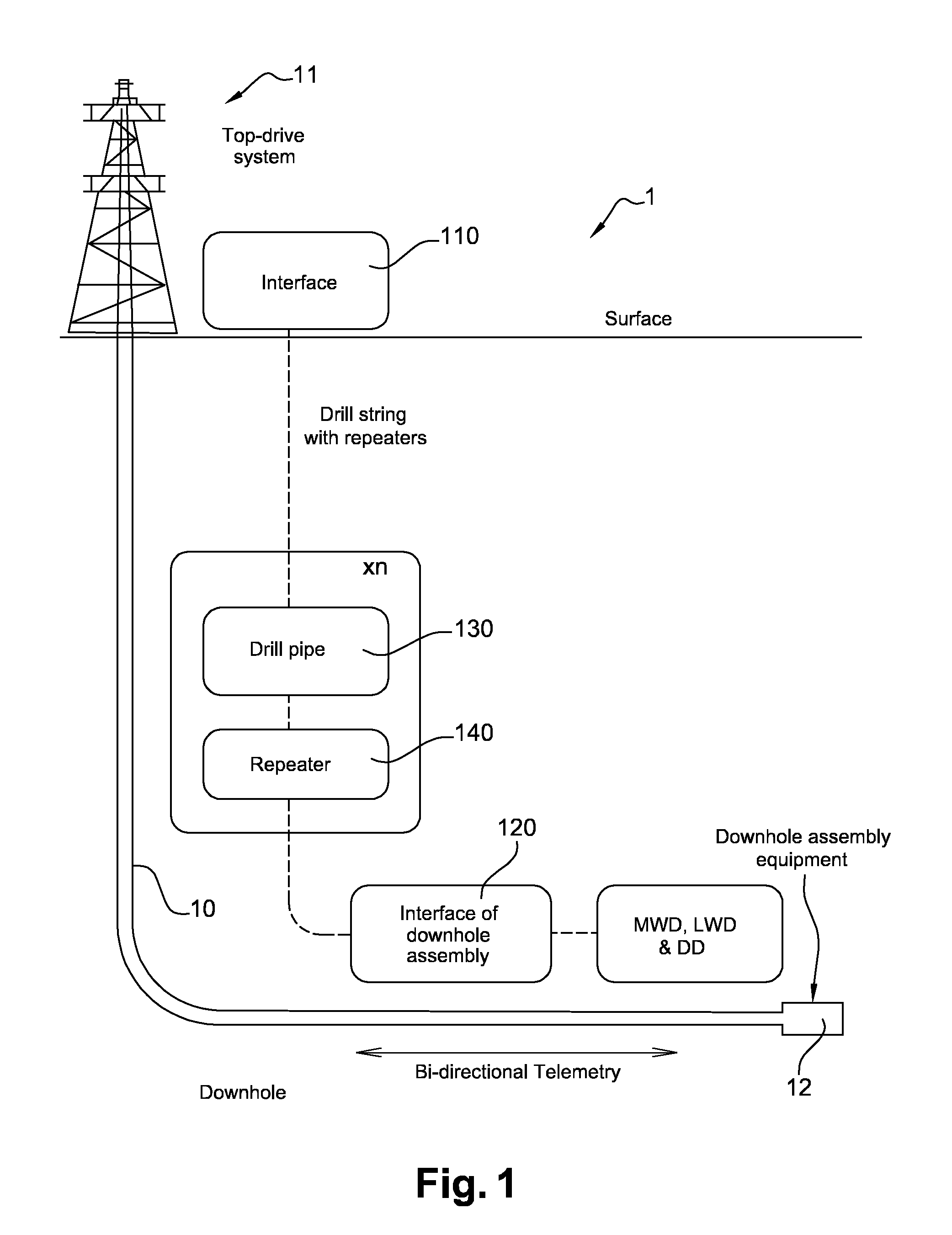
[0065]The invention will be described, in at least one of its embodiments, with reference to the example of the drilling installation of FIG. 1. In this drilling installation, the pipes according to the present invention are equipped with a large-diameter tubular coaxial transmission line. The invention is of course not limited to this particular example, and may apply to any pipe, which one intends to equip with a data transmission function, in addition to its initial function of conveying substances.

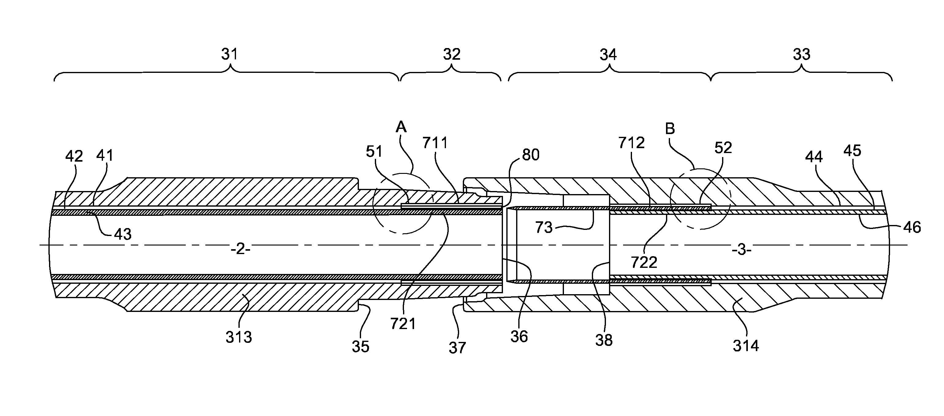
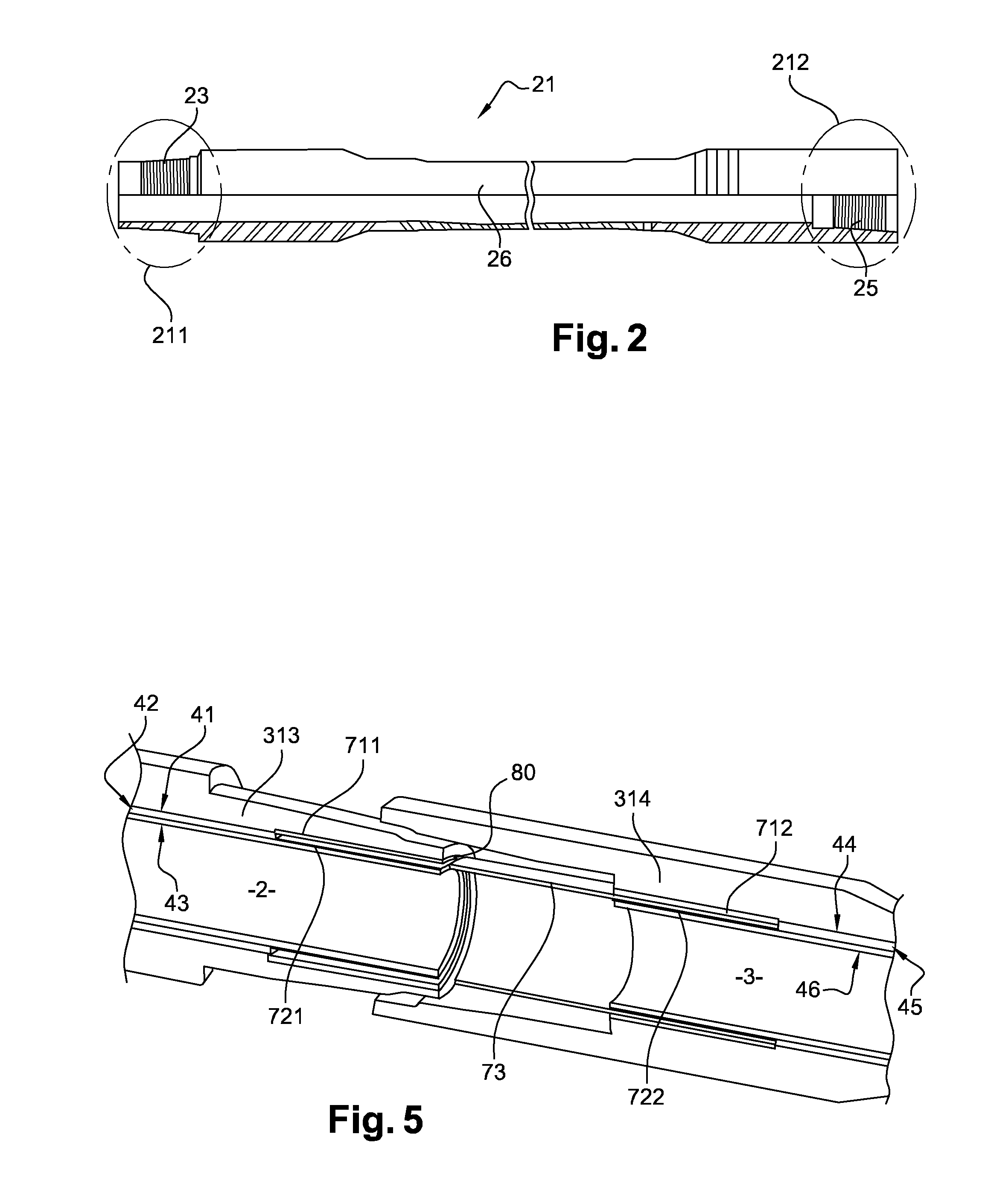
[0066]FIG. 2 is a cross-sectional view of a section of drill pipe 21 including a large-diameter tubular coaxial transmission line according to a particular embodiment of the present invention. As it will be described hereafter in relation with FIGS. 3, 4, and 5, it is proposed to connect two successive large-diameter tubular coaxial transmission lines by means of an electromagnetic coupler. In the example shown, this coupler is in annular form.

[0067]The depicted section 21 includes a p...


PUM


Abstract

An ensemble including a pipe for transporting substances which can flow, the pipe having a structure forming a coaxial transmission line including: a first tubular layer of electrically conductive material; a second tubular layer of electrically conductive material; and at least one first layer of dielectric material mounted in-between the first and the second layers of electrically conductive material, such that: the first layer of electrically conductive material forms an outer conductor of a section of the coaxial transmission line; the second layer of electrically conductive material forms an inner conductor of the section of the coaxial transmission line, and further including an electromagnetic coupler coupling the coaxial transmission line with a complementary coaxial transmission line carried by a pipe complementary to the pipe.

Description

1. FIELD OF THE INVENTION[0001]The present invention relates to the field of pipes dedicated for conveying substances (i.e. liquids and gases (fluids), slurries, powders, masses of small solids, etc.) which can flow, particularly (but not exclusively) pipes suitable for use in downhole environments, such as drill pipes used in oil and gas exploration. The present invention particularly relates to a system for transmitting data at high data rates through pipes of this type.2. TECHNOLOGICAL BACKGROUND[0002]It is sought more particularly here below in this document to describe problems existing in the field of drilling pipes. The invention of course is not limited to this particular field of application, but is of interest for any technique that implements a structure comprising at least one pair of successive pipes through which it is intended to transmit data.[0003]For illustrative purposes, FIG. 1 depicts a drilling installation 1 comprising a string of drilling tools 10 that convey...

Claims


Application Information

Patent Timeline
Patent Type & Authority Applications(United States)
IPC IPC(8): E21B17/00E21B17/02
CPCE21B17/028F16L9/02E21B17/003F16L25/01F16L15/001
Inventor CHABAS, JEAN-ALAINMINNIS, BRIAN
Owner BAKER HUGHES INC
Why Eureka
Try Eureka