Supercharge Your Innovation With Domain-Expert AI Agents!

Connector assembly for gas appliances

a technology for connecting parts and gas appliances, applied in the field of connecting parts, can solve problems such as gas leakage, complicated structure, and inconvenient operation

Active Publication Date: 2016-04-26
CHUNG CHIU CHIH
View PDF13 Cites 3 Cited by
  • Summary
  • Abstract
  • Description
  • Claims
  • Application Information

AI Technical Summary

Benefits of technology

The connector assembly allows for easy movement of gas appliances while preventing gas leakage by enabling bi-directional rotation, ensuring a secure and leak-proof connection between the appliance and the gas supply.

Problems solved by technology

However, the structure is complicated and the operation is inconvenient.
Furthermore, it has only one rotating direction and easy to result in gas leakage after the hose is twisted many times.

Method used


Image

  • Connector assembly for gas appliances
  • Connector assembly for gas appliances
  • Connector assembly for gas appliances

Examples


Embodiment Construction

[0020]Referring now to the drawings where like characteristics and features among the various figures are denoted by like reference characters.

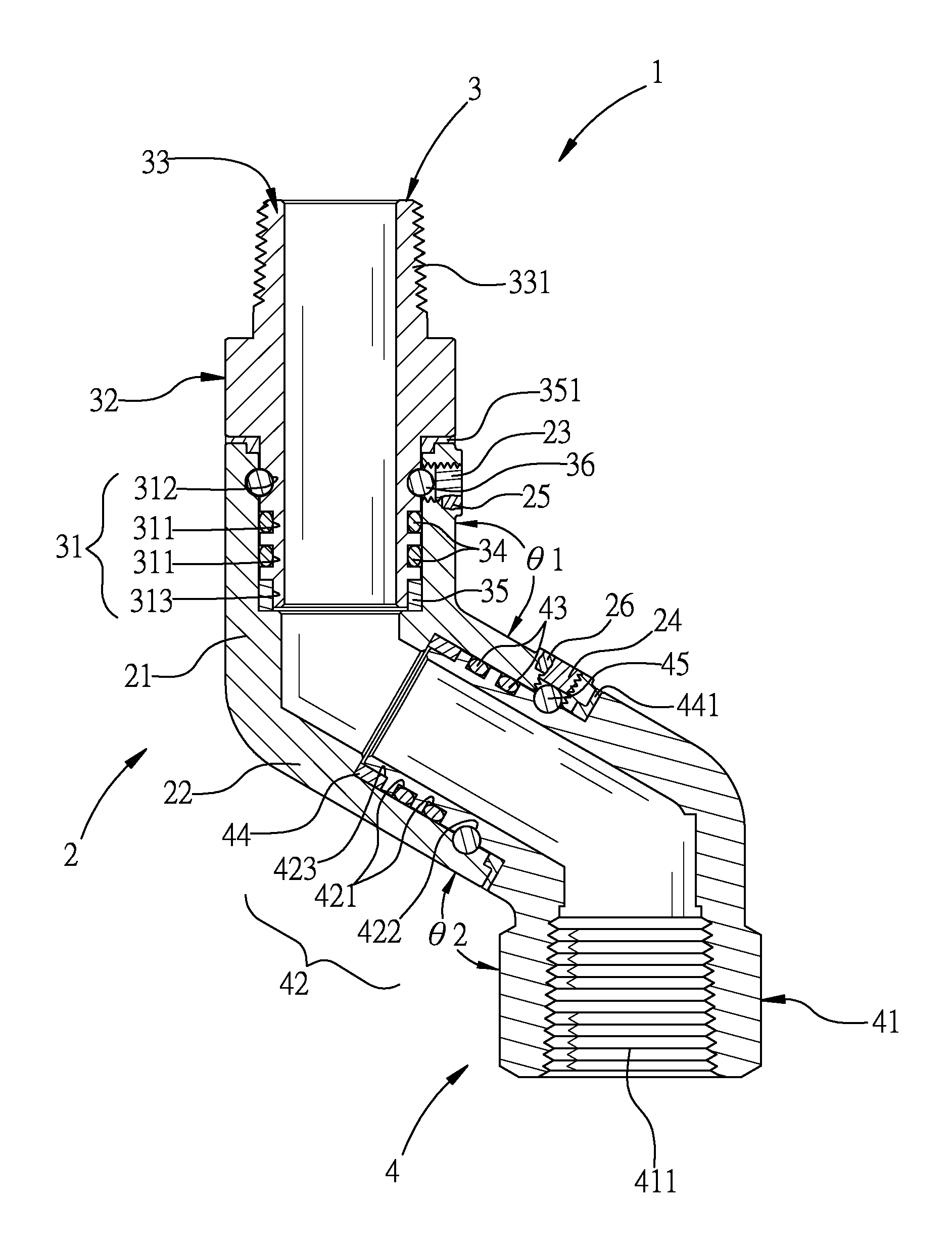
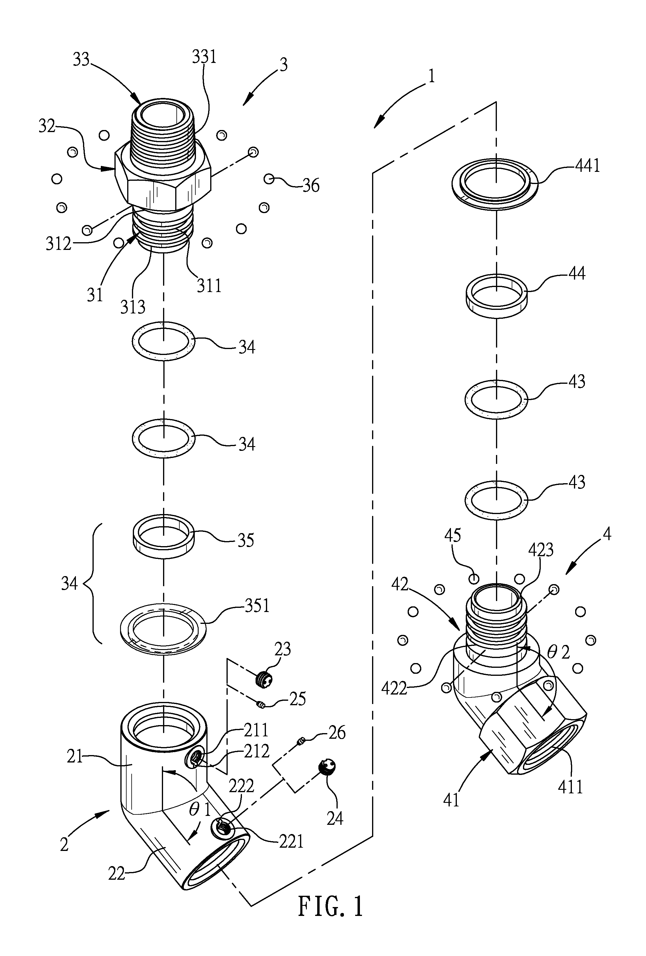
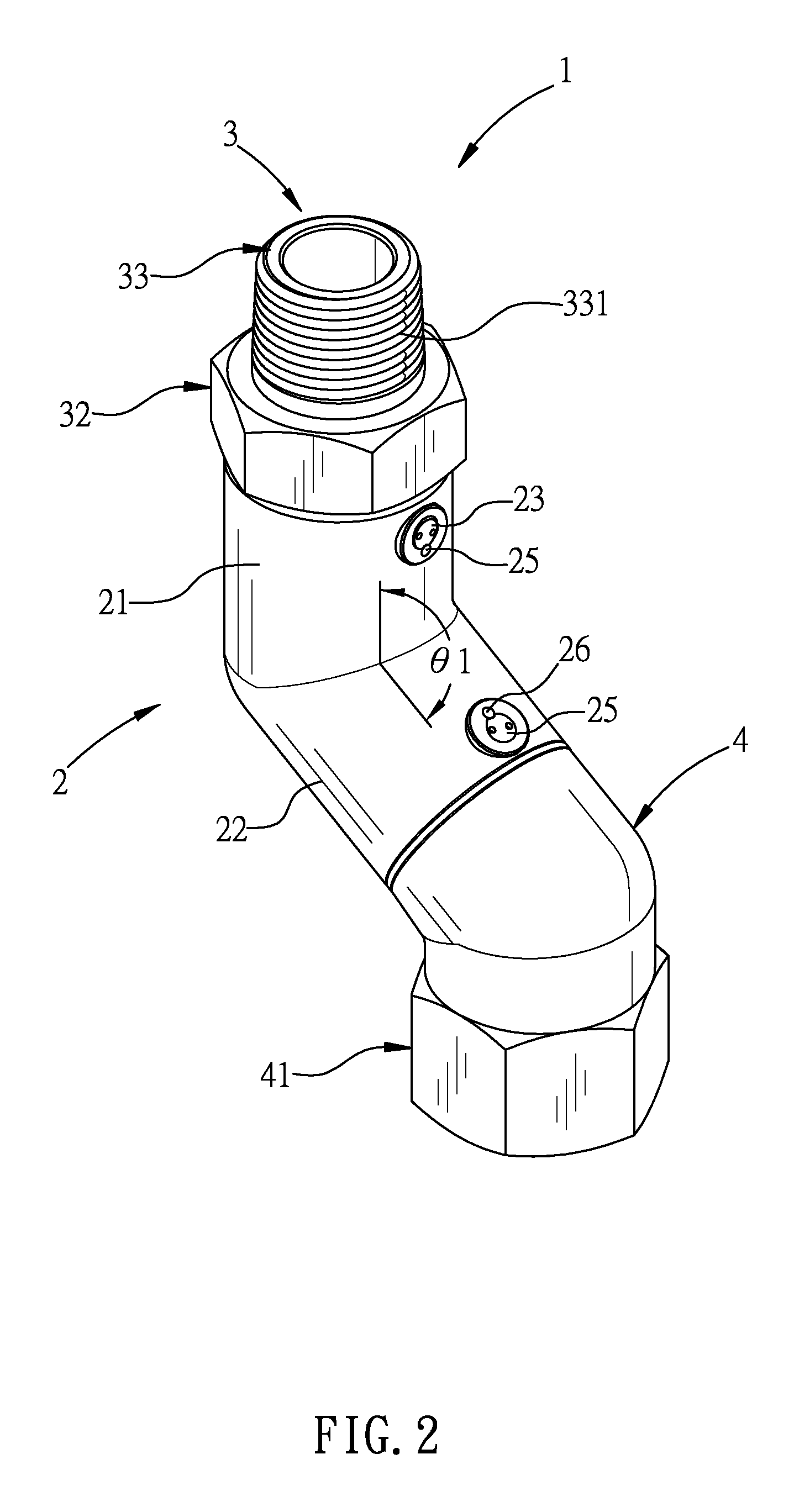
[0021]FIG. 1 is an exploded view of a connector assembly according to this present invention. FIG. 2 is an outside view of the connector assembly according to this present invention. FIG. 3 is a sectional view of the connector assembly according to this present invention. FIG. 4 is a perspective view of the connector assembly according to this present invention while the first screw pipe rotates relative to the first pipe portion. FIG. 5 is a perspective view of the connector assembly according to this present invention while the second screw pipe rotates relative to the second pipe portion. FIG. 6 is a view of the spring tension control of the connector assembly according to this present invention while being used at a gas appliance.

[0022]Please refer to FIGS. 1 and 6, the connector assembly 1 of this invention may comprise a connecting pipe...


PUM


Abstract

A connector assembly for gas appliances is disclosed. The connector assembly may be used in pairs and the composite hose may be fluidly connected therebetween. It may include two rotating direction. That is, the first screw pipe may rotate relative to the first pipe portion of the connecting pipe in the first rotating direction, and the second screw pipe may rotate relative to the second pipe portion of the connecting pipe in the second rotating direction which is different from the first rotating direction. It is easy to move the gas appliance relative to the gas supply and then prevents from gas leakage which results from the composite hose being twisted many times.

Description

FIELD OF THE INVENTION[0001]The present invention relates to a connector, and more particularly to a connector assembly for gas appliances.BACKGROUND OF THE INVENTION[0002]Commercial gas fired appliances, such as fryers, ranges and stoves, used in restaurants and other commercial and institutional kitchens, must be moved frequently to permit cleaning beneath and behind them as well as for enabling maintenance, repairs and inspections. Such appliances can weigh several hundred pounds and are equipped with casters to facilitate movement.[0003]Connectors for delivering gas to commercial gas fired appliances have been constructed to permit movement without disconnecting the gas supply lines. One proposal was to construct the connector from lengths of rigid pipe connected together by relatively rotatable sealed swivel joints so that the pipe assembly was flexed and straightened and the appliance moved toward and away from its normal operating location.[0004]Even though the pipe assemblie...

Claims


Application Information

Patent Timeline
Patent Type & Authority Patents(United States)
IPC IPC(8): F16L27/08F16L21/035F16L21/08
CPCF16L27/0849F16L21/035F16L21/08F16L27/0828F16L27/0841F16L27/0861F24C3/126
Inventor CHUNG, CHIU-CHIH
Owner CHUNG CHIU CHIH
Features
  • R&D
  • Intellectual Property
  • Life Sciences
  • Materials
  • Tech Scout
  • Unparalleled Data Quality
  • Higher Quality Content
  • 60% Fewer Hallucinations
Learn More