Device and method for deboning bone-in leg

a bone-in leg and leg bone technology, which is applied in meat processing devices, butchering, poultry processing, etc., can solve the problems of reducing the yield of meat, reducing the quality of bone-in meat, and difficult cooking of thigh meat, so as to eliminate variations in shape, simplify the process step, and accurately measure the length of the knee joint and the entire length of the bone-in leg.

Active Publication Date: 2016-05-03
MAYEKAWA MFG CO LTD
View PDF19 Cites 10 Cited by
  • Summary
  • Abstract
  • Description
  • Claims
  • Application Information

AI Technical Summary

Benefits of technology

[0012]In view of the above problems of the conventional art, an object of the present invention is to implement a deboning process capable of increasing the yield of meat during cutting and forming deboned meat into an attractive shape to thereby enhance the quality and the commercial value of the deboned meat when the deboning process in which the bone-in leg is separated into the lower thigh and the thigh and the thigh is separated into the thigh meat and the thigh bone is performed. In addition, another object thereof is to implement a deboning device in which the above deboning process is automated.
[0027]According to the present invention, since the incision is made in the thigh from the knee joint to the head of the thigh bone, the thigh meat after the separation does not become tubular but is opened, and hence it is possible to enhance the quality and the commercial value of the thigh meat as deboned meat, and accurately position the cutting blade and the meat separator at each process step. As a result, the shape of each of the lower thigh and the thigh does not vary, and it is possible to improve the yield of each of the lower thigh and the thigh. In addition, it is possible to implement the device in which the deboning process shown in FIG. 12 is fully automated.

Problems solved by technology

As a result, the amount of meat remaining on the thigh bone is increased so that the yield of the meat is reduced, and the thigh meat is tubular so that a problem arises that the appearance and quality as the deboned meat are deteriorated and the thigh meat is difficult to cook.
In addition, a problem arises that the lower thigh cannot be separated from the thigh by cutting accurately at the position of the knee joint so that the shape of each of the lower thigh and the thigh varies, and the yield of each of the lower thigh and the thigh is thereby reduced.

Method used


Image

  • Device and method for deboning bone-in leg
  • Device and method for deboning bone-in leg
  • Device and method for deboning bone-in leg

Examples


Embodiment Construction

[0043]Hereinbelow, the present invention will be described in detail by using an embodiment shown in the drawings. Note that the scope of the present invention is not limited only to dimensions, materials, shapes, and relative arrangements of constituent parts described in the embodiment unless specifically described.

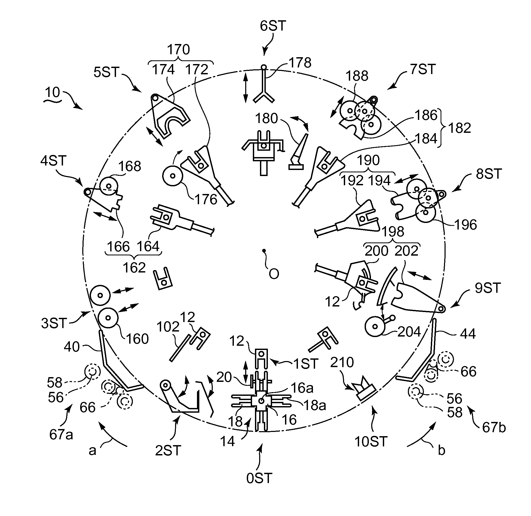
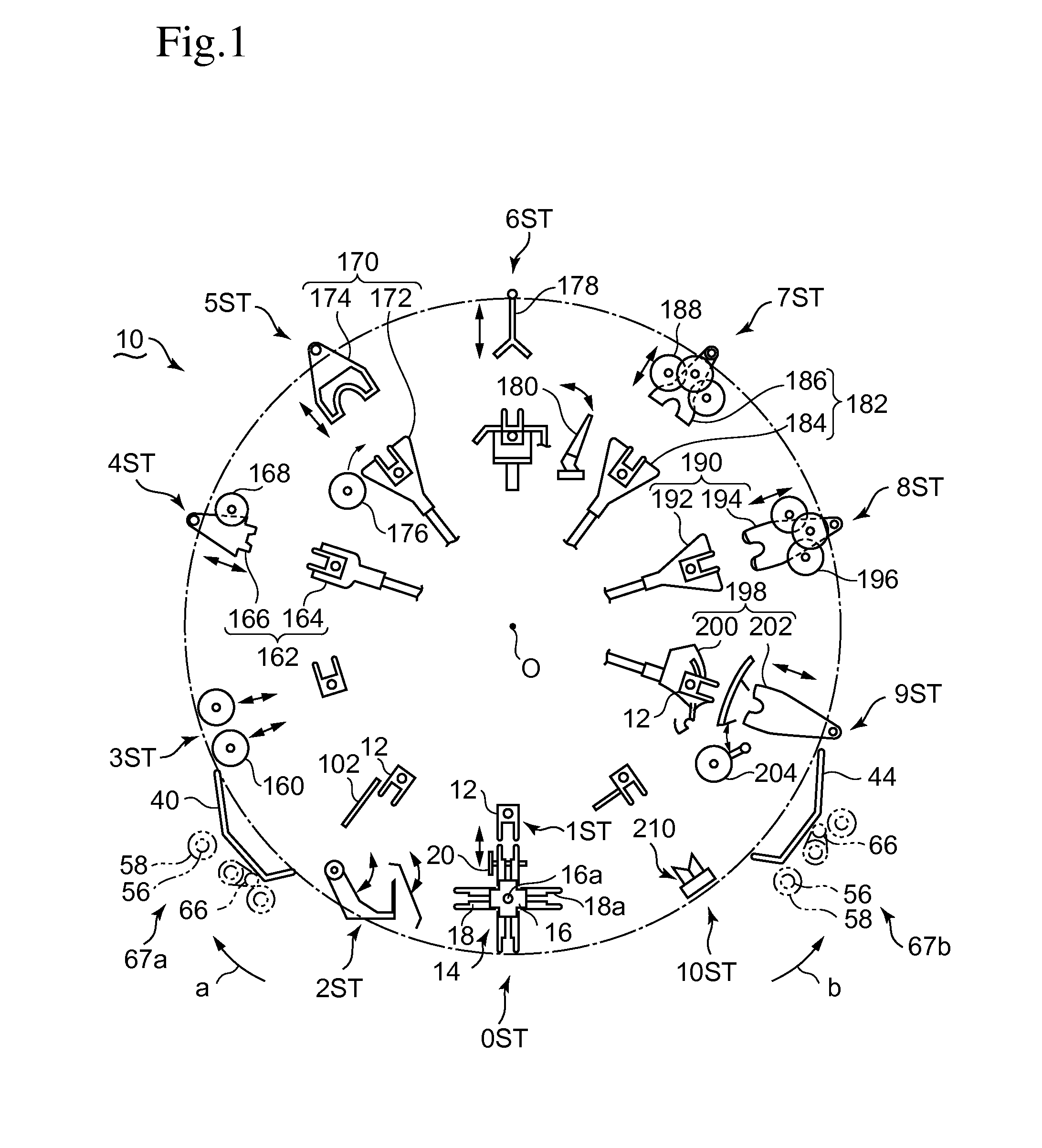
[0044]One embodiment in which the present invention is applied to a deboning process of a bone-in leg of a poultry carcass will be described based on FIGS. 1 to 11. FIG. 1 is a view schematically showing an overall structure of a deboning device 10. The deboning device 10 is an automatic deboning device configured to be capable of executing the deboning method disclosed in WO 2011 / 121899 (hereinafter referred to as a “prior deboning method 1”) and a deboning method of the present invention. The deboning device 10 is configured by one assembly in which process stations which perform steps from loading of a bone-in leg (hereinafter referred to as a “work”) to the final st...


PUM


Abstract

In a deboning process, a knee joint length is measured in a work loading section of a first process station, and incision making of a thigh meat portion is performed in a second process station based on the measured knee joint length. At the same time, the entire length of a work is measured, and the knee joint length is calculated from previously collected data based on the measured entire length of the work. Positioning of a cutting blade and a meat separator is performed based on these values in subsequent process stations, and cutting of a tendon adhering to a knee joint and tearing of thigh meat are performed. A thigh bone is separated from a lower thigh in a further process station.

Description

RELATED APPLICATIONS[0001]The present application corresponds to Japanese Application Number 2012-134371 filed Jun. 14, 2012, the disclosure of which is hereby incorporated by reference herein in its entirety.BACKGROUND OF THE INVENTION[0002]1. Field of the Invention[0003]The present invention relates to a deboning device and a deboning method used in a deboning process of a bone-in leg of a poultry carcass or the like.[0004]2. Description of the Related Art[0005]A deboning process of a bone-in leg of a livestock carcass such as a poultry carcass has been conventionally developed for the purpose of saving labor, improving yield, and stabilizing the shape of deboned meat. The bone-in leg has a muscle and a tendon which firmly couple a bone portion and a meat portion in the vicinity of a knee joint, and hence it is necessary to accurately cut them. Japanese Patent Application Laid-open No. H11-333894 discloses a technique in which an incision making step of the bone-in leg of the poul...

Claims


Application Information

Patent Timeline
Patent Type & Authority Patents(United States)
IPC IPC(8): A22C17/00A22C21/00
CPCA22C21/0076A22C21/0053
Inventor KIDO, KOJIGOTO, OSAMUKODAMA, RYUJI
Owner MAYEKAWA MFG CO LTD
Why Eureka
Try Eureka