Method, apparatus and chemical products for treating petroleum equipment

a petroleum equipment and chemical technology, applied in the direction of hydrocarbon oil treatment, heating types, hydrocarbon distillation, etc., can solve the problems of plant equipment fouling, coke and coke-like deposits, process equipment fouling,

Active Publication Date: 2016-05-03
FERRARA
View PDF28 Cites 5 Cited by
  • Summary
  • Abstract
  • Description
  • Claims
  • Application Information

AI Technical Summary

Benefits of technology

[0060]An embodiment includes a method wherein the treatment reduces plant catalysts agglomeration and / or reduces coke formation on plant catalysts and / or reduces heavy compounds deposits, including coke, on plant catalysts and / or reduces differential pressure in a plant reactor containing a catalyst.
[0122]An embodiment of the invention includes a method of designing a plant that is suited (but not limited to) providing the performance of one or more of the above described, compatible treatment method embodiments, and features a plant design wherein plant equipment that is subject to treatment is designed under not conservative conditions, wherein there is avoided inputting into the equipment a greater than 20% fouling factor (e.g., having a fouling factor level of 0 to less than 20%) as well as the avoidance of the presentment of any fouling back up equipment in the plant design in the relevant area (e.g., in the closed or semi-closed loop).
[0123]An embodiment of the invention includes a method of manufacturing of a plant comprising rendering into a physical plant based on a plant design wherein the equipment subject to treatment is designed under not conservative conditions, wherein there is avoided inputting into the equipment a greater than 20% fouling factor (e.g., having a fouling factor level of 0 to less than 20%) as well as the avoidance of the presentment of any fouling back up equipment in the plant design such as in the relevant treatment area described above.
[0126]adjusting of the fresh feed by increasing the plant fresh feed rate from an established feed rate to a level above the established feed rate as to generate an additional quantity of distillates relative to a quantity generated at the established feed rate, and drawing off at least some of an overall quantity of distillate generated from the increased plant feed rate and introducing the drawn off distillate into a treatment region of said plant for enabling the cleaning of heavy deposits from one or more pieces of equipment in the treatment region.

Problems solved by technology

Generally speaking, fouling of process equipment arises from deposition of heavy compounds.
Sometimes degradation can even lead to coke and coke-like deposits.
Petroleum plants suffer from fouling of equipment.
It is to be considered, even crude oil just as extracted gives rise to fouling problems within the industrial plant arising from heavy compounds precipitation inside production equipment.
For example, oil-gas separators, stabilization / distillation columns, heat exchangers, and filters are subject to such fouling.
Once the crude oil is processed in refining plants, these refining plants also experience heavy compound fouling.
All of the hydrocarbon processing industry is experiencing this problem from oil fields to refining and petrochemical plants, as well as fine chemicals production.
In all of the above exemplary cases, fouling reduces plant performance and makes it necessary for equipment shutdown, placement out of service, decommissioning, cleaning and subsequent commissioning and then getting it back on-stream.
In any case, fouling associated costs imply: i) energy costs, as it is more difficult to supply or exchange heat when the equipment is fouled, with related increase in fuel consumption; ii) production loss costs, as fouling limits throughput and / or plant yields or can lead to an anticipated shutdown; iii) maintenance costs, such as a specialized company mechanically cleaning the equipment; iv) environmental costs, as waste is generated, and needs to be disposed of, (with related waste disposal costs); environmental burdens, together with waste disposal, generation of emissions of airborne pollutants, included those related to increased fuel consumption.
The above costs are almost inevitable with current technologies.
The above operations, besides having the mentioned drawbacks, can also cause damage to the equipment to be cleaned.
For heat exchanger bundles to be extracted, e.g., their lifting by means of crane and slings or an extractor is required: this causes bundle bending and in turn damage to tubes and boring; furthermore, removal and re-assembling of floating heads might lead to potential leaking when the gasket is not perfectly placed.
Air / steam decoking of furnaces, besides prolonged downtime, might lead to carburation of coils which might cause tube rupture.
Finally, in a petroleum plant, cleaning of equipment is performed for each single piece of equipment, with different timing, and is a labor intensive job.
This is a serious technical problem because cleaning implies reduced / stopped production of the plant and / or of said equipment.
In the state of the art, the main technical problem which hampers the cleaning of the equipment during a plant run is attributable to the stoppage of plant production and / or the stoppage of the normal flow which passes through said equipment in order to clean it.
In the state of the art it was not thinkable to achieve the equipment cleaning during plant run because all of the existing techniques implied the stoppage of the normal flow which passes through said equipment.

Method used


Image

  • Method, apparatus and chemical products for treating petroleum equipment
  • Method, apparatus and chemical products for treating petroleum equipment
  • Method, apparatus and chemical products for treating petroleum equipment

Examples


example n.1

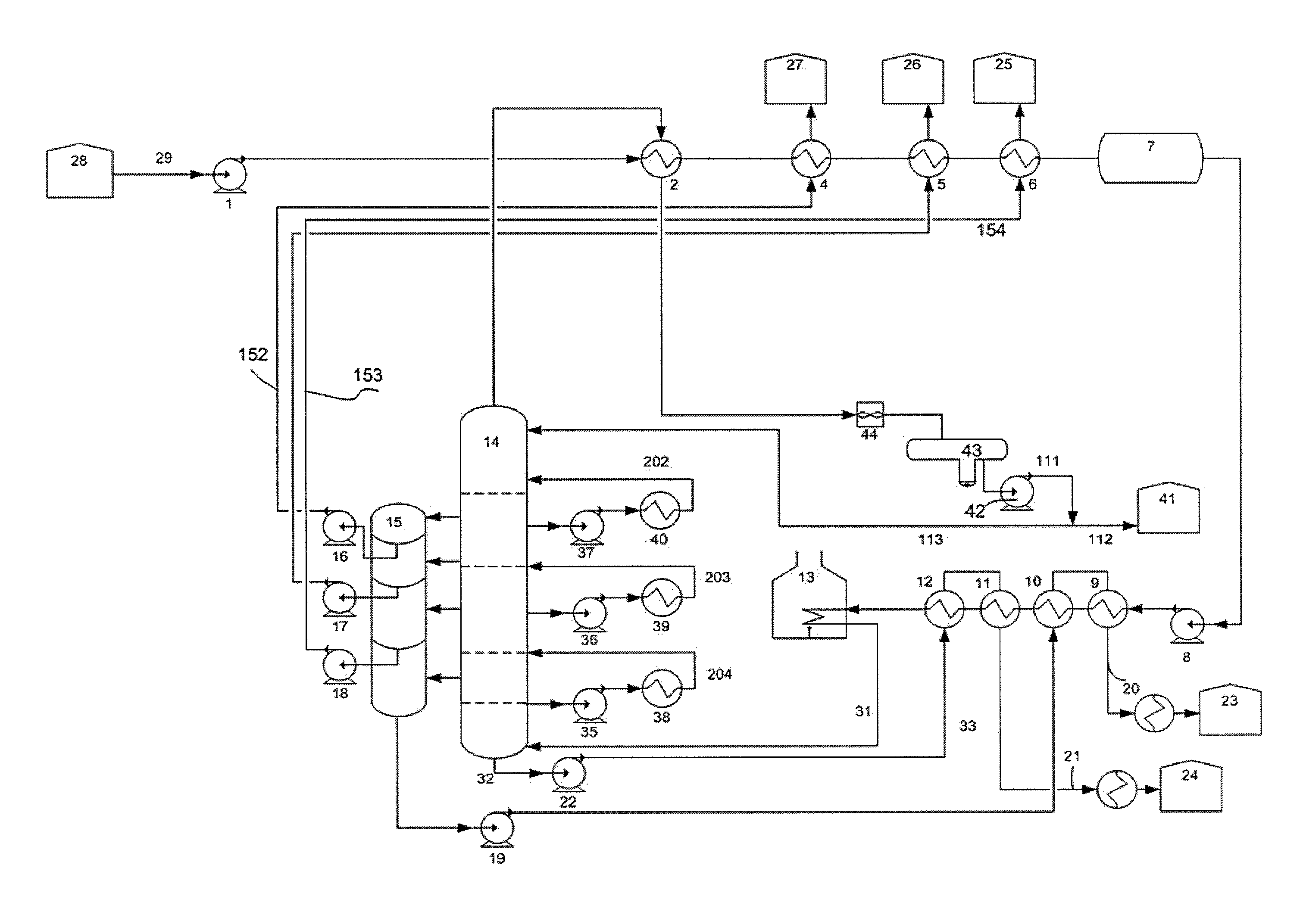
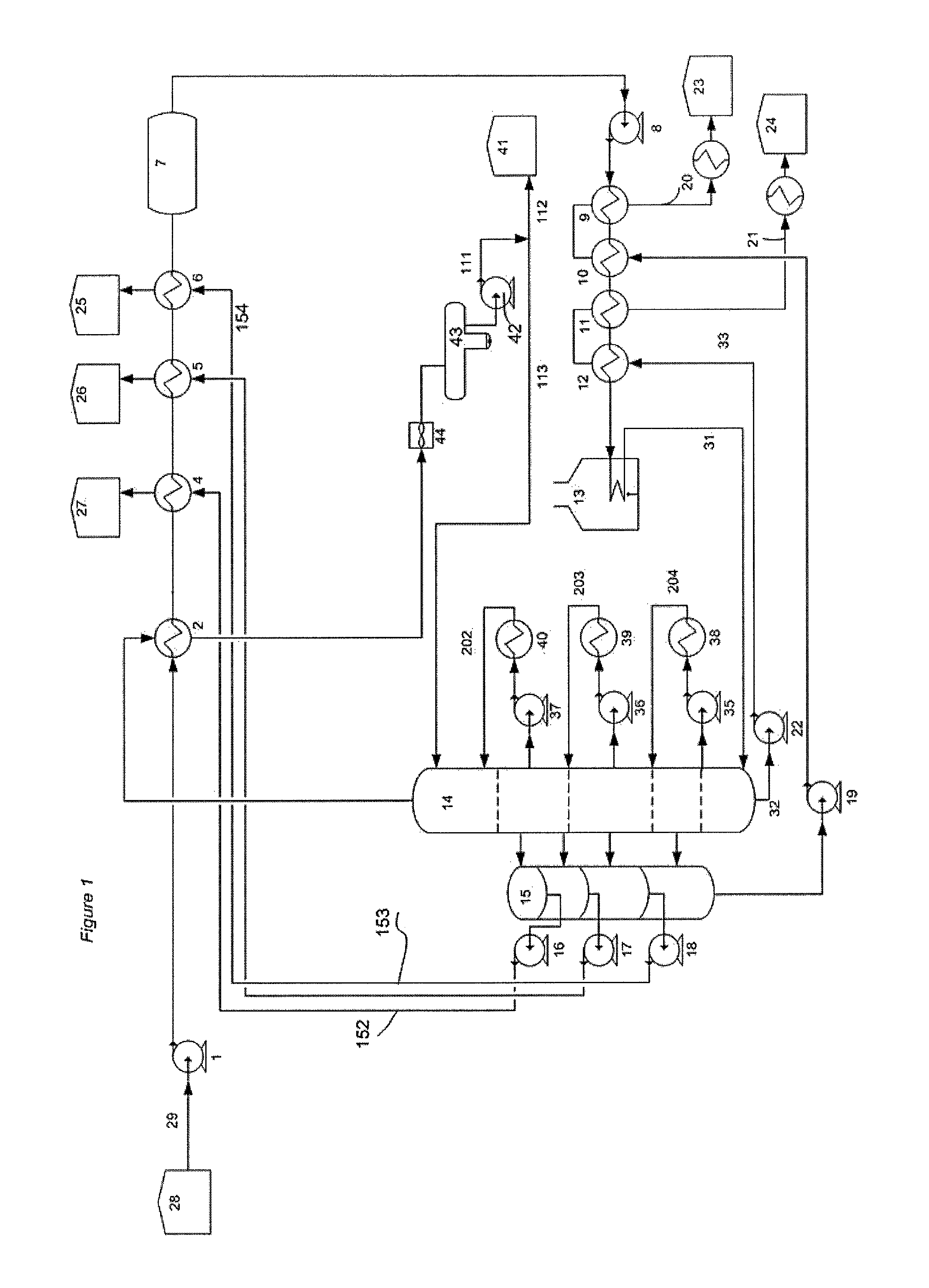
[0345]A crude atmospheric distillation plant (CDU) has a design throughput of 500 tons per hour (T / h) and a technical minimum throughput of 250 T / h. Based on design throughput there have also been designed downstream plants, which receive the products resulting from distillation as well as distillation residue. The distillation yield of the typical processed crude is: 20% gasoline, 20% kerosene, 30% gas oil, 30% atmospheric residue. At the design throughput this corresponds to 100 T / h gasoline, 100 T / h kerosene, 150 T / h gas oil, 150 T / h atmospheric residue. When the fresh feed rate is 250 T / h, a yield of 50 T / h gasoline, 50 T / h kerosene, 75 T / h gas oil, 75 T / h atmospheric residue will be achieved. The plant is however designed to manage a production up to 150 T / h gas oil and a feed of 500 T / h, therefore it is possible to introduce in the plant, in one or more points (e.g., in the feed), up to 75 T / h gas oil (e.g., coming from storage). In this latter case therefore, the feed will be...

example n.2

[0346]The crude atmospheric distillation plant (CDU) of example 1 runs at a fresh feed flowrate of 400 T / h, therefore the production will be 80 T / h gasoline, 80 T / h kerosene, 120 T / h gas oil, 120 T / h atmospheric residue. The fresh feed rate is then increased to 500 T / h, and the “exceeding” 30 T / h gas oil will be re-introduced and circulated in the plant. The fresh feed rate is then decreased back to 400 T / h and the gas oil “exceeding” the one of normal production will be re-introduced and circulated in the plant. The plant can thereafter continue to run under these conditions (fresh feed 400 T / h, circulating self-produced gas oil 30 T / h) or by reducing, e.g., the fresh feed to 300 T / h, by having 60 T / h of “exceeding” gas oil re-introduced and circulated in the plant. The fresh feed can then be reduced to 250 T / h, thereby distilling 150 T / h gas oil. From the distilled 150 T / h gas oil, e.g., 75 T / h will exit the plant to satisfy production needs, while 75 T / h will be re-introduced in ...

example n.3

[0349]With reference to FIG. 12, during the normal run, two feed pumps (401) and (403) are running, while the pump (402) is idle and in stand-by as a spare of (401) and (403. The same applies to the booster pump (500), a spare of (501) and (502), which during the normal run will have the valves (516) and (517) closed. Moreover, all of the cold train exchangers (from 404 to 408 and from 503 to 507), the desalters (409 and 508) and all of the hot train exchangers (from 410 to 416 and from 509 to 515), are inserted in the production cycle (valves 427, 428, 518, 520, 437, 438, 529, 530 opened). Hereinafter are exemplary described the operations, under the present invention, to clean one hot preheat line, while the other preheat line is inserted in the production cycle and allows for the run of the plant. In order to realize the present invention, e.g., to clean one hot preheat line, firstly the valves (518), (520) are closed to isolate the equipment to be cleaned; the valves (516) and (...


PUM

PropertyMeasurementUnit
pressureaaaaaaaaaa
pressureaaaaaaaaaa
temperatureaaaaaaaaaa

Abstract

The present invention provides a method, an apparatus and chemical products for treating petroleum equipment wherein a fluid is flowing, preferably of the hydrocarbon type, and wherein treating is performed by establishing a closed or semi-closed flow circulation loop, during the normal production operations of the equipment. The treatment can refer to the cleaning of equipment, to yield improvement as compared to normal run conditions and / or to a reduction of coke formation and / or to coke removal on catalysts.

Description

CROSS REFERENCE TO RELATED APPLICATIONS[0001]This application claims benefit of U.S. Provisional Application No. 61 / 624,629 filed Apr. 16, 2012 as well as Italian Application No. ITRM20120162 filed on Apr. 16, 2012. These priority applications are incorporated herein by reference.BACKGROUND OF THE INVENTION[0002]The present invention is inclusive of a method, an apparatus and chemical products for cleaning petroleum equipment, preferably of the hydrocarbon processing type, wherein cleaning is performed by establishing a closed or semi-closed flow circulation loop, during the normal production operations of said equipment.[0003]The present invention is further inclusive of a method, an apparatus and chemical products for increasing distillation yields of a petroleum plant.[0004]The present invention is also inclusive of a monitoring system to verify the cleaning status during execution of the claimed method.[0005]The present invention is still further inclusive of a method, an appara...

Claims


Application Information

Patent Timeline
Patent Type & Authority Patents(United States)
IPC IPC(8): C10G75/04F24D17/00F24D17/02
CPCC10G75/04F24D17/0021F24D17/0031F24D17/02Y10T29/49C10G9/16C10G2300/4075C10G7/00C10G9/005C10G9/007C10G45/02
Inventor FERRARA
Owner FERRARA
Why Eureka
Try Eureka