Devices and methods for minimally invasive spinal stablization and instrumentation

a spinal stablization and instrumentation technology, applied in the field of devices and methods for minimally invasive spinal stablization and instrumentation, can solve the problems of increased confusion and loss of direction in intra-operative surgery, significant pain, deformity and disability, and difficulty compounded

Active Publication Date: 2016-05-24
STRYKER EUROPEAN OPERATIONS LIMITED
View PDF30 Cites 22 Cited by
  • Summary
  • Abstract
  • Description
  • Claims
  • Application Information

AI Technical Summary

Benefits of technology

[0016]In one aspect provided is a method for fusion of a first vertebral bone and a second adjacent vertebral bone of a subject. The method includes identifying a first pedicle of the first vertebral bone on radiographic imaging; identifying the second adjacent vertebral bone on radiographic imaging and a first facet joint. The first facet joint forms an articulation between the first vertebral bone and the second adjacent vertebral bone. The first facet joint resides on the same side of the vertebral midline as the identified first pedicle of the first vertebral bone. The method also includes advancing a first threaded segment of a first bone fastener assembly into the identified first pedicle of the first vertebral bone. The first bone fastener assembly further includes a second segment that is adapted to couple with a distraction platform. The method also includes coupling the distraction platform with the second segment of the first bone fastener assembly. The distraction platform is adapted to concurrently attach onto at least one tissue retention blade. The method further includes positioning the tissue retention blade in proximity to the first bone fastener assembly that is anchored to the pe

Problems solved by technology

Whether from degenerative disease, traumatic disruption, infection or neoplastic invasion, alteration in the anatomical relationships between the spinal vertebras can cause significant pain, deformity and disability.
Unfortunately, an oblique operative corridor is less familiar to surgeons and contains fewer recognizable anatomical landmarks—leading to a higher rate of intra-operative confusion an

Method used


Image

  • Devices and methods for minimally invasive spinal stablization and instrumentation
  • Devices and methods for minimally invasive spinal stablization and instrumentation
  • Devices and methods for minimally invasive spinal stablization and instrumentation

Examples


Embodiment Construction

[0071]In order to promote an understanding of the principals of the disclosure, reference is made to the drawings and the embodiments illustrated therein. Nevertheless, it will be understood that the drawings are illustrative and no limitation of the scope of the invention is thereby intended. Any such alterations and further modifications in the illustrated embodiments, and any such further applications of the principles of the invention as illustrated herein are contemplated as would normally occur to one of ordinary skill in the art.

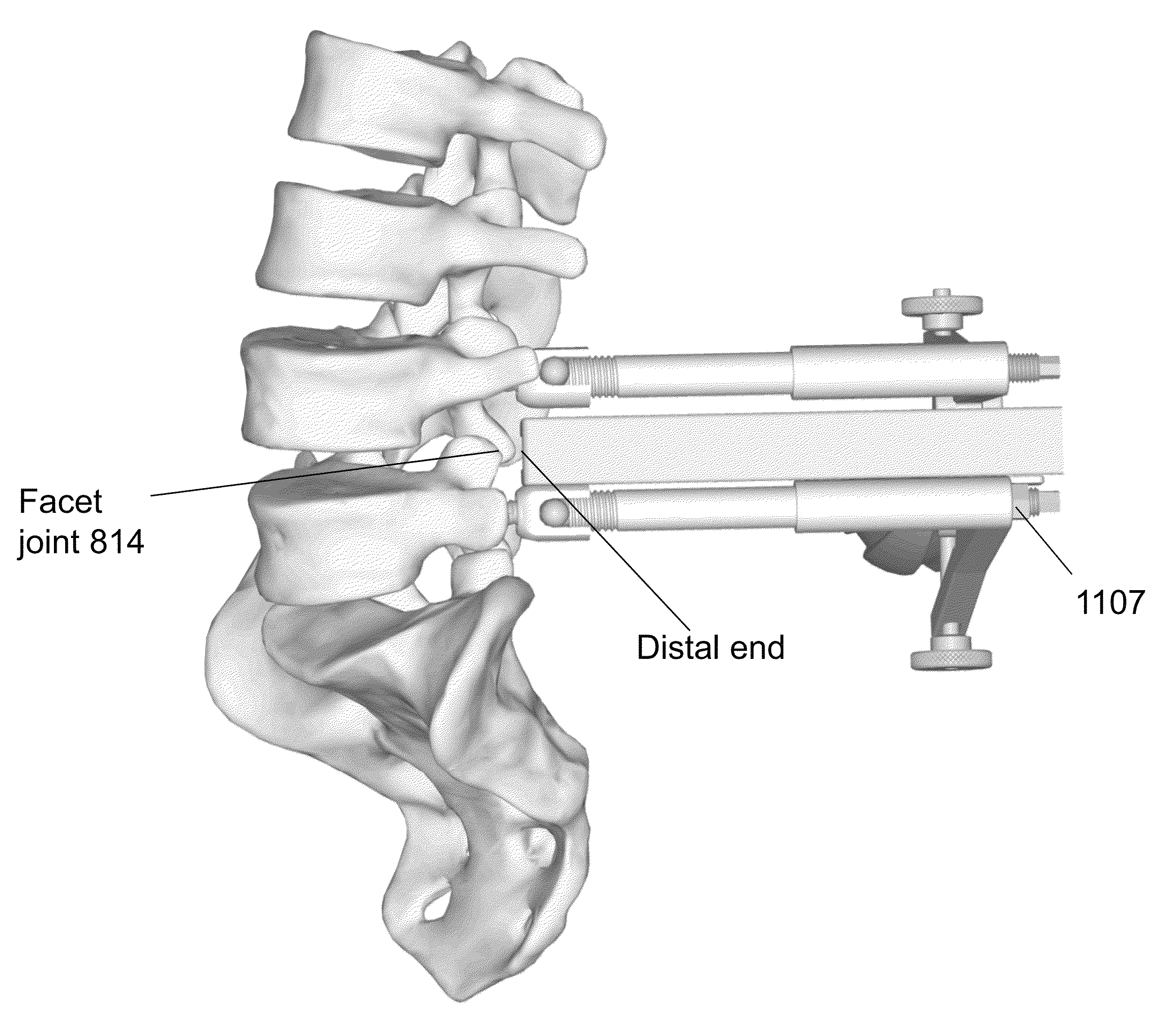
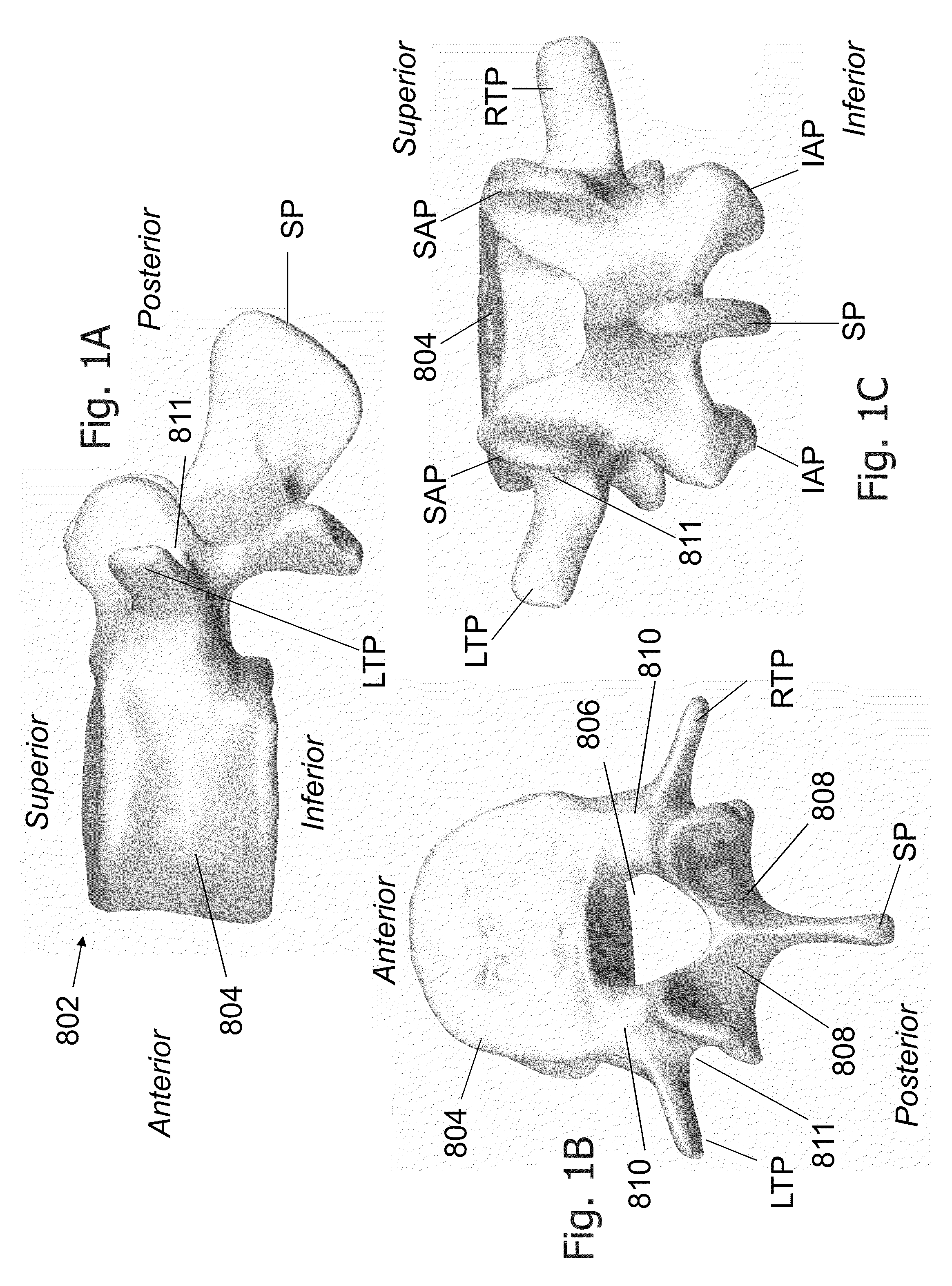
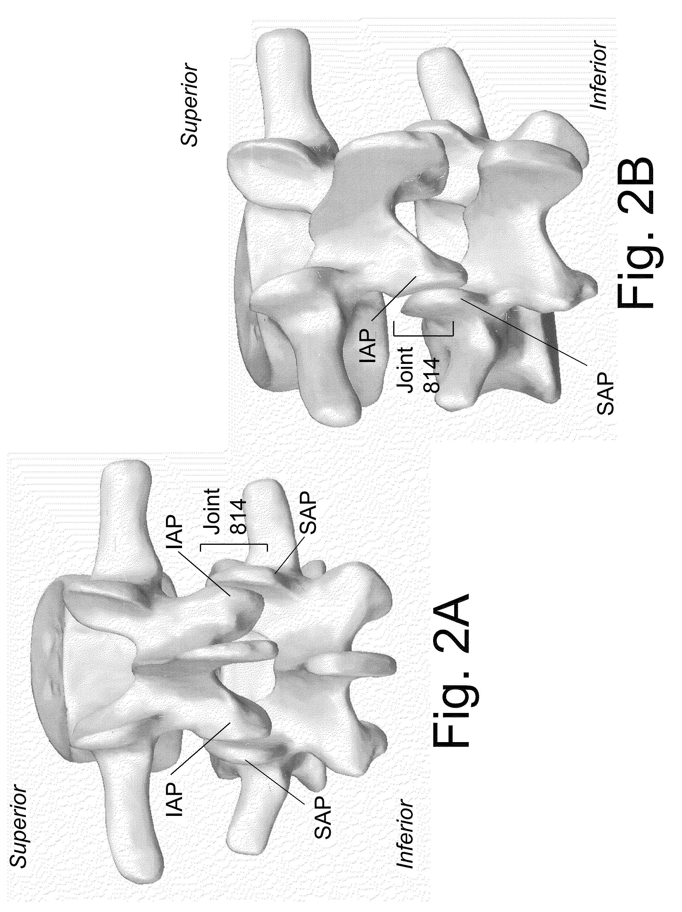
[0072]FIG. 1 shows a diagrammatic representation of a spinal vertebral bone 802 in multiple views. For clarity of illustration, the vertebral bone of FIG. 1 and those of other illustrations presented in this application are represented schematically and those skilled in the art will appreciate that actual vertebral bodies may include anatomical details that are not shown in these figures. Further, it is understood that the vertebral bones at a given l...


PUM


Abstract

Described herein are devices and methods for fusion of adjacent vertebral bones using distractor platforms for exposure and resection of at least a portion of the facet joint, such as in performance of a TLiF procedure. In one embodiment, the distractor platform contains at least a first receptacle and/or extension adapted to couple to the implanted screw/bone marker and the method includes advancing a threaded segment of a bone fastener assembly into the identified first pedicle of the first vertebral bone, the first bone fastener assembly further comprises a second segment adapted to couple with a distraction platform adapted to concurrently attach onto at least one tissue retention blade and adapted to retain the tissue retention blade in the displaced position. Stabilization of a spinal segment is also provided by advancing a substantially concave orthopedic implant through an opening made in a posterior aspect of a disc space.

Description

CROSS-REFERENCE TO PRIORITY DOCUMENT[0001]This application is a divisional of and claims priority to co-owned, co-pending U.S. patent application Ser. No. 14 / 320,349 filed on Jun. 30, 2014 of the same title, and incorporated herein by reference in its entirety, which is a continuation of and claims priority to co-owned U.S. patent application Ser. No. 13 / 875,228 filed on May 1, 2013 of the same title, issued as U.S. Pat. No. 8,764,806 on Jul. 1, 2014, and which is a continuation of and claims priority to co-owned U.S. patent application Ser. No. 12 / 962,534 filed on Dec. 7, 2010 of the same title, and which claims priority of co-owned U.S. Provisional Patent Application Ser. No. 61 / 283,745, entitled “Devices and Methods for Minimally Invasive Spinal Stabilization and Instrumentation”, filed Dec. 7, 2009. Priority of the aforementioned filing date is hereby claimed and the disclosure of the provisional patent application is hereby incorporated by reference in its entirety.BACKGROUND[0...

Claims


Application Information

Patent Timeline
IPC IPC(8): A61B17/70A61B17/16A61F2/44A61B17/02A61B17/17A61B17/88A61B17/56A61F2/46A61B17/00A61F2/30
CPCA61B17/025A61B17/0206A61B17/0218A61B17/1611A61B17/1757A61B17/708A61B17/7032A61B17/7037A61B17/7082A61B17/88A61F2/4455A61F2/4611A61B2017/00473A61B2017/0256A61B2017/564A61F2002/30131A61F2002/30772A61F2002/4485A61F2002/4635A61F2310/00359A61B17/7083A61B17/7077A61B17/7079A61B2017/681A61F2/442A61F2002/4435
Inventor ABDOU, SAMY
Owner STRYKER EUROPEAN OPERATIONS LIMITED
Why Eureka
Try Eureka