
System for obtaining vehicular traffic flow data from a tire pressure monitoring system

a technology of traffic flow and monitoring system, which is applied in the field of monitoring surface roadway vehicular traffic flow and traffic conditions, can solve the problems of high accuracy and inability to send accurate traffic flow data to the motoring public, and achieve the effect of improving crowd sourcing accuracy and increasing sampling ra

Active Publication Date: 2016-05-24
LIVE TRAFFIC DATA
View PDF10 Cites 22 Cited by
  • Summary
  • Abstract
  • Description
  • Claims
  • Application Information

AI Technical Summary

Benefits of technology

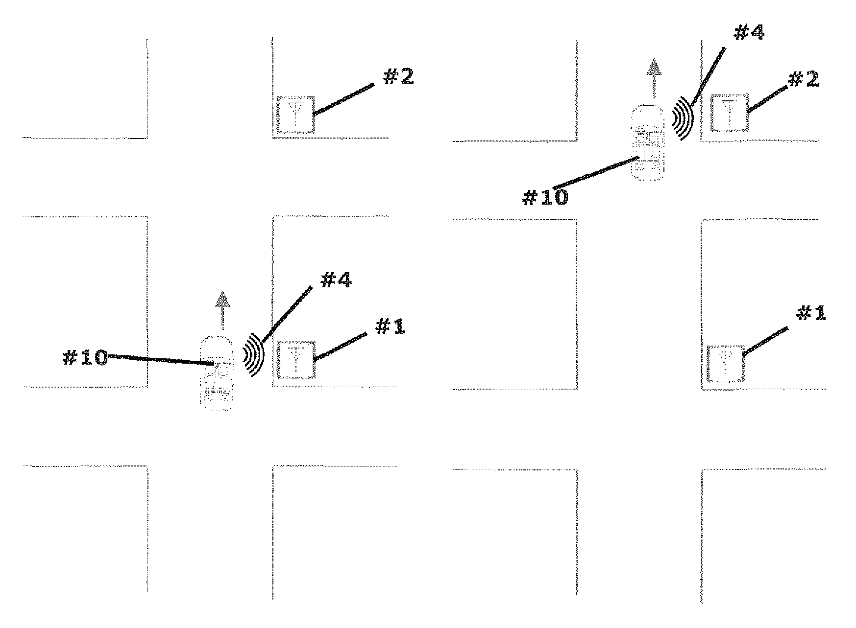
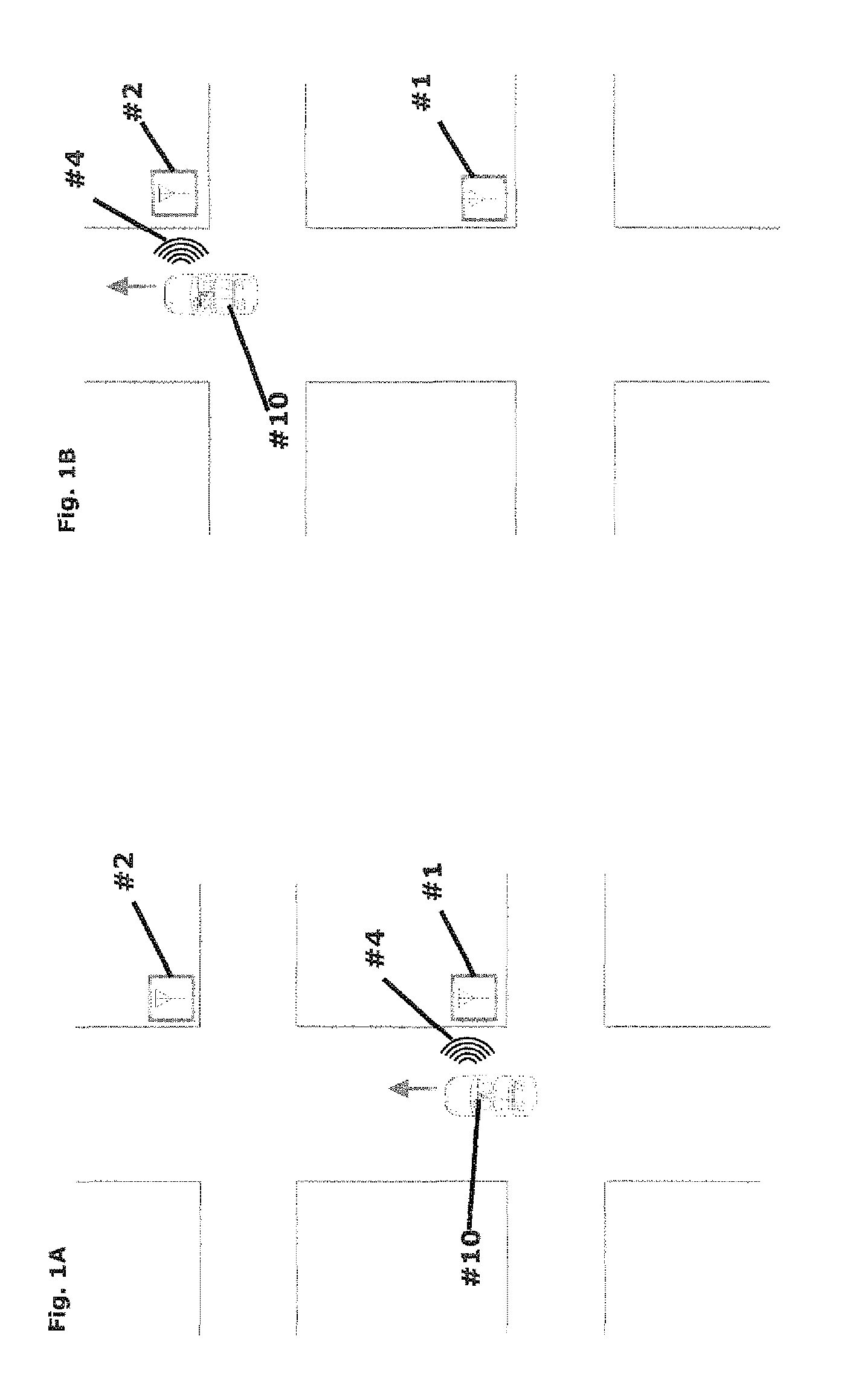
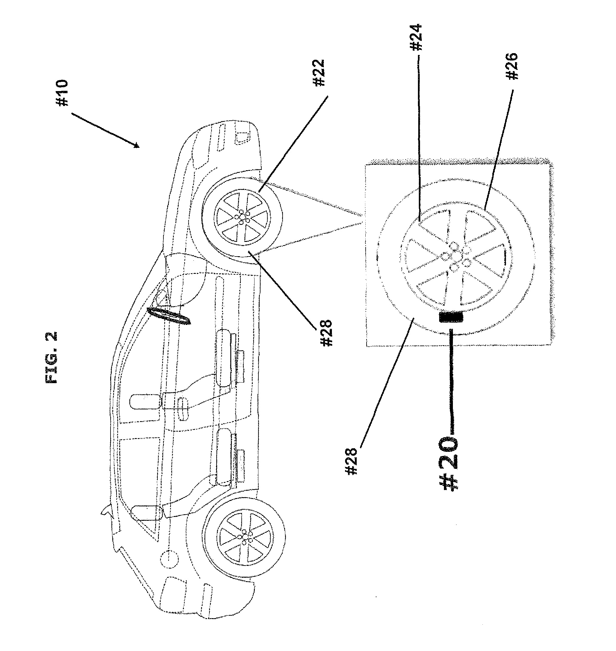
The present invention is a surface transportation vehicular wheel based monitoring system that uses a Tire Pressure Monitoring System (TPMS) to estimate traffic flow data. The system consists of an encrypted central server and a group of encrypted TPM sensor detection transceivers that receive the TPM sensors in the vehicle wheels. The TPM sensors broadcast pressure and temperature information continuously in real-time. The transceivers capture the RF signal and decode it to obtain the unique identification code associated with a specific TPM sensor. The system can distinguish between mobile data sources outside a vehicle and on or inside a vehicle, accurately calculating surface vehicle traffic flow. The invention improves the accuracy of traffic flow data and provides valuable information to the motoring public.

Problems solved by technology

The prior art discovered relies on crowd sourcing which is a new phenomena now omnipresent in large surface traffic data companies (i.e. INRIX, Google Maps, etc.) which does not lend to accurate traffic flow data readings being sent to the motoring public.
This method has been proven, in a recent study by the University of Michigan October 2013 study of GPS live traffic data companies, to be highly inaccurate as Smartphones, regardless of whether they are actually traveling with the owner in a vehicle or just with walking pedestrians, will send out data to the central server which has no ability to differentiate.

Method used


Image

  • System for obtaining vehicular traffic flow data from a tire pressure monitoring system
  • System for obtaining vehicular traffic flow data from a tire pressure monitoring system
  • System for obtaining vehicular traffic flow data from a tire pressure monitoring system

Examples


Embodiment Construction

[0026]Although specific embodiments of the present invention will now be described with reference to drawings, it should be understood that such embodiments are by way of example only and merely illustrative of but a small number of the many possible specific embodiments what can represent applications of principles of the current invention. Various changes and modifications obvious to one skilled in the art to which the present invention pertains are deemed to be within the spirit, scope and contemplation of the present invention.

[0027]The present invention is a method or system to accurately estimate traffic flow data comprised of, but not limited to, travel times and vehicular origin-destination from vehicles equipped with a Tire Pressure Monitoring System (TPMS). Vehicles are required to be equipped with TPMS by their original manufacturers in accordance to the Federal TREAD Act of 2000. The TPM sensors of a four-wheel vehicle include four sensors each with a unique identificati...


PUM


Abstract

An embedded Tire Pressure Monitoring sensor is incorporated into vehicular wheels and a secured central server is used to track the unique identification code of each sensor. The TPMS is installed by the vehicular manufacturer in accordance with the federally mandated TREAD Act of 2000. When a vehicle enters the radius of a first encrypted TPM sensor detection transceiver, its TPM sensor identification codes are recorded and time-stamped via an encrypted TPM sensor detection transceiver. If the vehicle enters the area of a second encrypted TPM sensor detection transceiver, the sensor codes will be recorded and time-stamped a second time, encrypted and sent to the secured central server. Using the two encrypted, time-stamped signals, the secured central server calculates traffic flow data.

Description

CROSS-REFERENCE TO RELATED APPLICATION[0001]This patent application claims priority to Provisional Application No. 62 / 050,966 filed on Sep. 16, 2014.BACKGROUND OF THE INVENTION[0002]1. Field of the Invention[0003]The present invention relates to monitoring surface roadway vehicular traffic flow and traffic conditions.[0004]2. Prior Art[0005]In general, the concept of monitoring surface roadways to compute the traffic flow and traffic conditions has been utilized in the prior art but in a different way from the unique features that will be discussed in the present invention.[0006]The closest prior art that is related to the general field of the invention in which the present invention is to be categorized is as follows.[0007]United States Patent 20110156924 for “ESTIMATION OF TRAVEL TIMES USING BLUETOOTH” issued on Jun. 30, 2011 to Nadeem, Tamer M. et al. The patent discloses methods for estimating travel time using at least two remote systems to record the timestamps associated with...

Claims


Application Information

Patent Timeline
Patent Type & Authority Patents(United States)
IPC IPC(8): G08G1/01H04L29/06G08G1/015B60C23/04
CPCG08G1/0133H04L63/0428G08G1/015B60C23/04B60C23/0408B60C23/0479G08G1/0112G08G1/0129G08G1/0141G08G1/096716G08G1/096741G08G1/096775G08G1/20H04L67/12H04W4/38
Inventor HOLZWANGER, MARKLIU, XIANGHONG HENRYZHENG, JIANFENGHU, HENGSUN, JIEHOLZWANGER, HARRYBLOCK, WILLIAM REID
Owner LIVE TRAFFIC DATA
Learn More