Transceiver and operating method thereof

Active Publication Date: 2016-05-24
UPI SEMICON CORP
View PDF7 Cites 2 Cited by
  • Summary
  • Abstract
  • Description
  • Claims
  • Application Information

AI Technical Summary

Benefits of technology

The invention is a transceiver that can automatically detect its configuration and improve its signal transmission speed, regardless of the number of isolators used. This improves the speed of signal transmission and reduces the cost of the transceiver.

Problems solved by technology

These four isolators ISO1˜ISO4 will not only occupy more space, but also increase the entire cost of the transceiver.

Method used


Image

  • Transceiver and operating method thereof
  • Transceiver and operating method thereof
  • Transceiver and operating method thereof

Examples


Embodiment Construction

[0030]Exemplary embodiments of the present invention are referenced in detail now, and examples of the exemplary embodiments are illustrated in the drawings. Further, the same or similar reference numerals of the elements / components in the drawings and the detailed description of the invention are used on behalf of the same or similar parts. In the following embodiments, if an element is “connected” or “coupled” to another element, the element may be directly connected or coupled to the another element, or there may be any elements or specific materials (e.g., colloid or solder) disposed between the element and the another element.

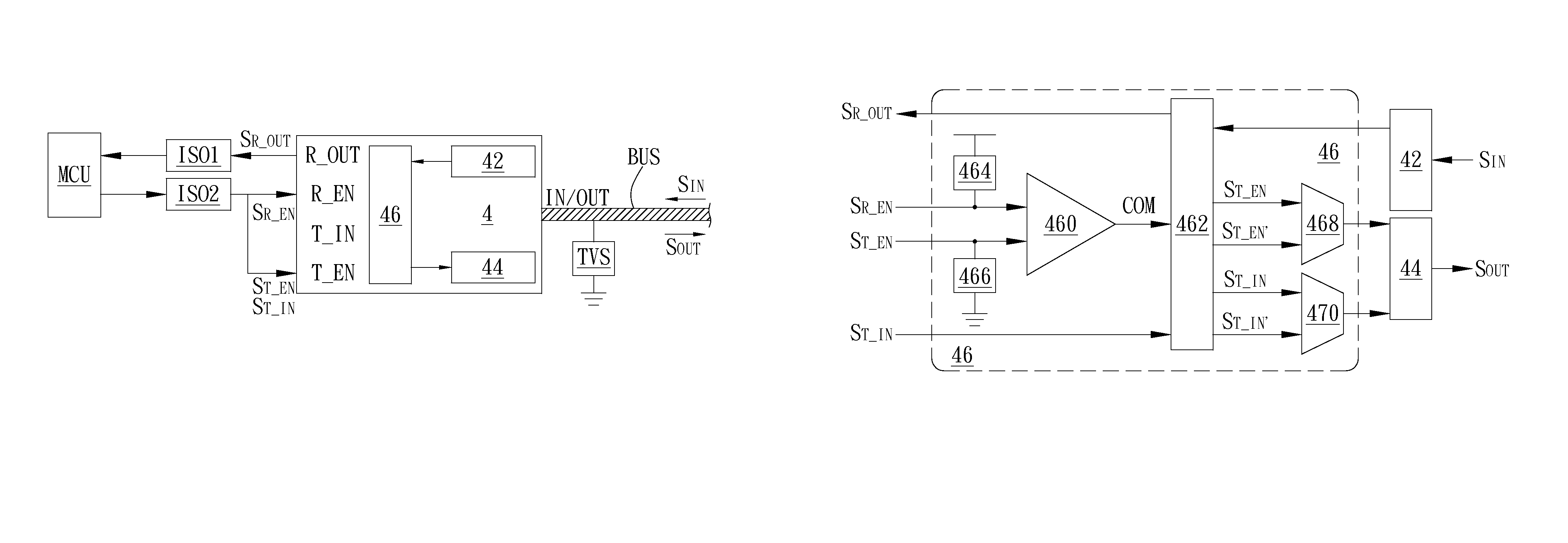
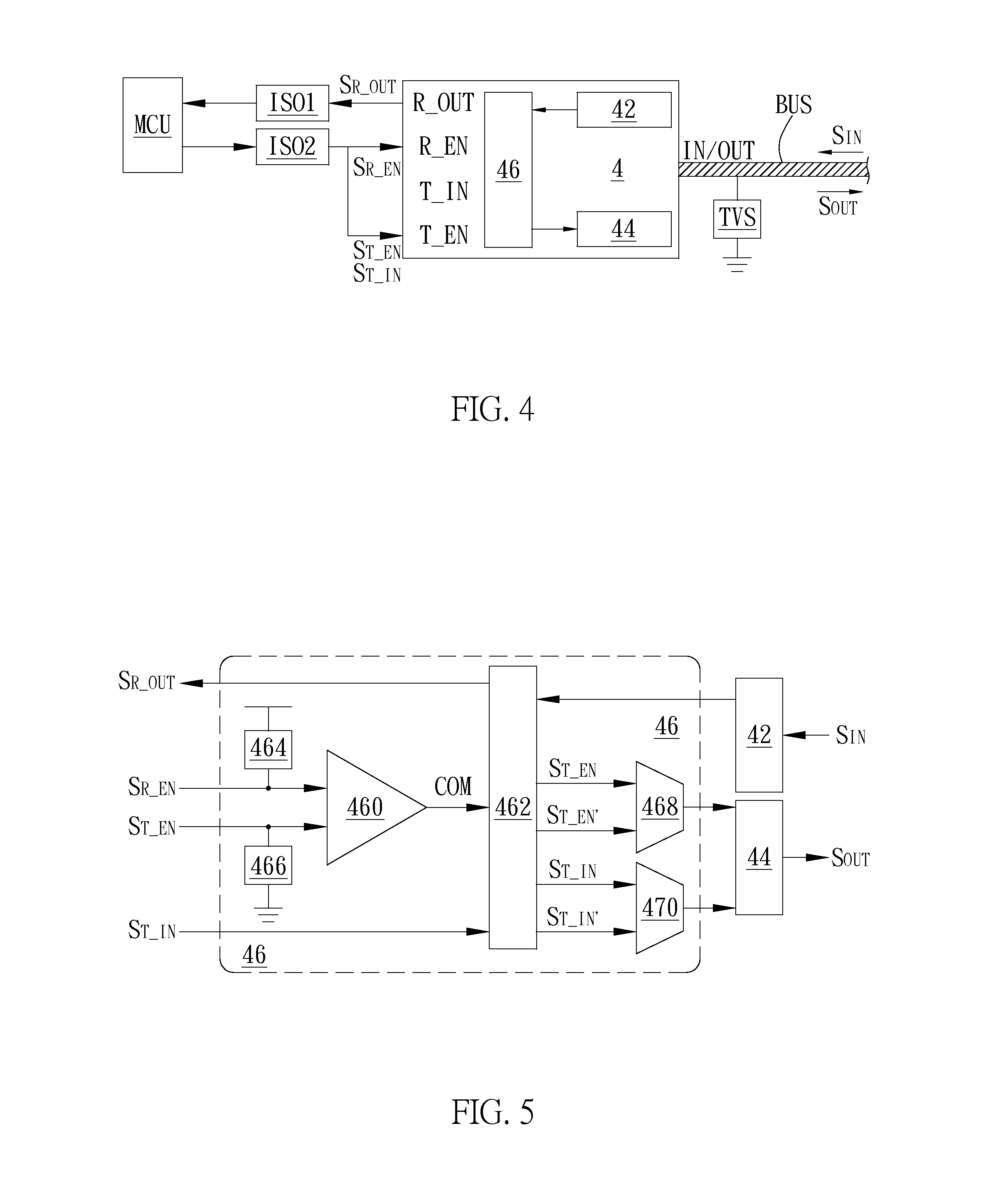
[0031]A preferred embodiment of the invention is a transceiver. In this embodiment, the transceiver is a half-duplex transceiver operated in the open drain configuration and used to transmit and receive all kinds of signals. It has advantages of low cost and high transmission rate and has high elasticity to use. No matter whether the transceiver of the inv...


PUM


Abstract

A transceiver and a transceiver operating method are disclosed. The transceiver is coupled to a bus. The transceiver includes a receiving unit, a transmitting unit, and a detection unit. The receiving unit is coupled to the bus. The transmitting unit is coupled to the bus. The detection unit is coupled to the receiving unit and the transmitting unit respectively. The detection unit receives a first input signal, a receiver enabling signal, and a transmitter enabling signal respectively and selectively enhances the first input signal and the transmitter enabling signal according to a result of comparing the receiver enabling signal and the transmitter enabling signal. Then, the detection unit transmits the enhanced first input signal and transmitter enabling signal to the bus through the transmitting unit.

Description

BACKGROUND OF THE INVENTION[0001]1. Field of the Invention[0002]The invention relates to a transceiver; in particular, to a transceiver and a transceiver operating method capable of transmitting signal in high speed and cooperating with isolators of different numbers.[0003]2. Description of the Prior Art[0004]In general, when two electronic apparatus communicate with each other, because different electronic apparatus may use different communication protocols to transmit signals, one electronic apparatus usually selects a transceiver corresponding to its communication protocol to normally communicate with the other electronic apparatus.[0005]In practical applications, as shown in FIG. 1, in order to prevent high energy impact and interference from outside, isolators ISO1 and ISO 2 can be disposed between a micro-processor MCU1 and a transceiver TR1 and between a micro-processor MCU2 and a transceiver TR2 respectively, so that the micro-processors MCU1 and MCU2 can be completely prote...

Claims


Application Information

Patent Timeline
IPC IPC(8): H04B1/38H04B17/19H04L12/40H04B17/18
CPCH04B1/38H04L12/40H04B17/18H04B17/19G06F13/4072H03K19/018585
Inventor CHEN, CHIH-HAO
Owner UPI SEMICON CORP
Why Eureka
Try Eureka