
Loadboard enhancements for automated test equipment

Active Publication Date: 2009-11-10
CREDENCE SYSTEMS
View PDF14 Cites 0 Cited by
  • Summary
  • Abstract
  • Description
  • Claims
  • Application Information

AI Technical Summary

Benefits of technology

[0007]Accordingly, a need exists for an enhanced loadboard which saves cost and more effectively utilizes loadboard real estate. Additionally, a need exists to decrease signal degradation associated with loadboards when transmitting high-speed signals. Further, a need exists for more direct pin-to-pin calibration which minimizes error interjection when calibrating with respect to a common reference pin. Embodiments of the present invention provide novel solutions to these needs and others as described below.
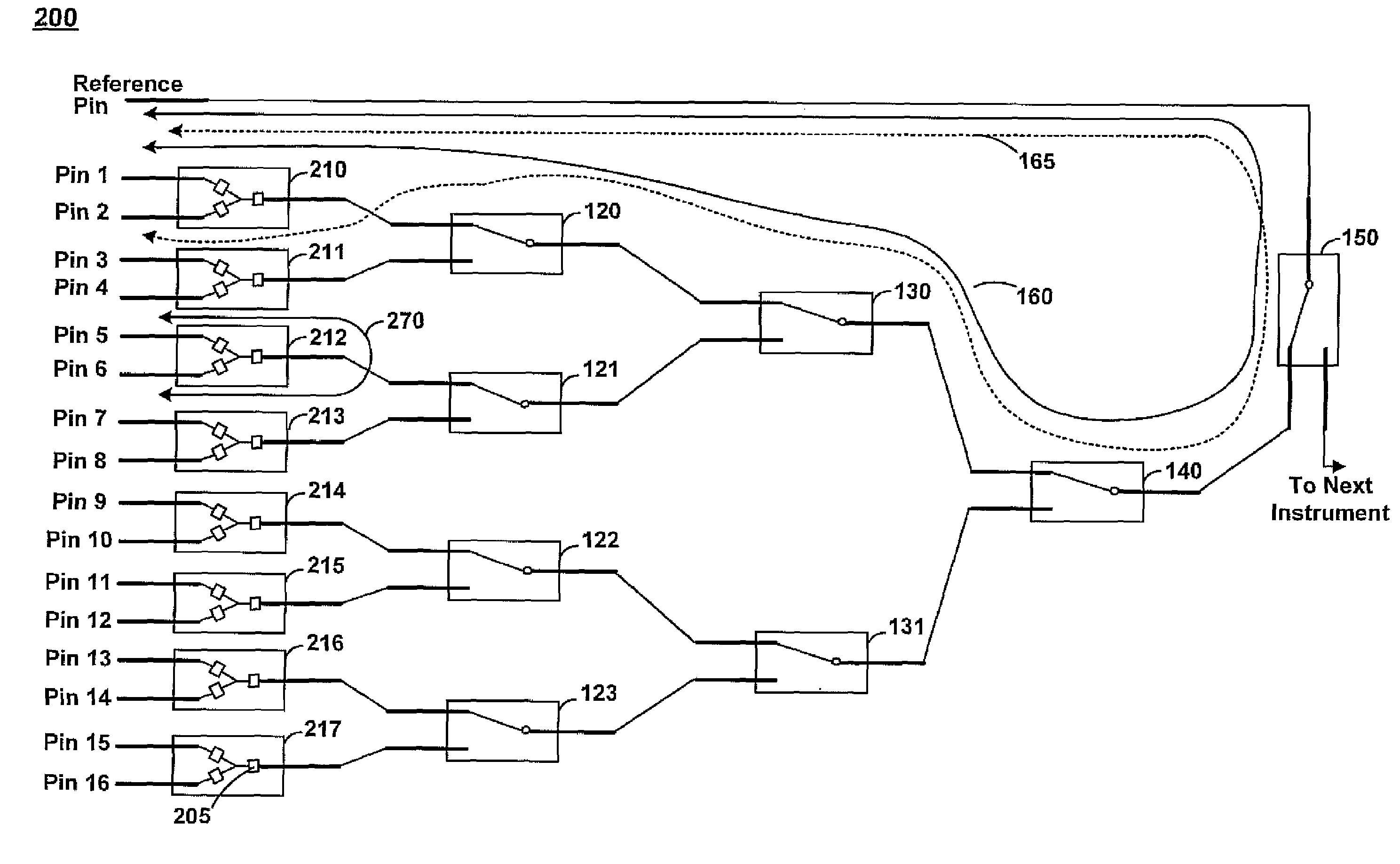
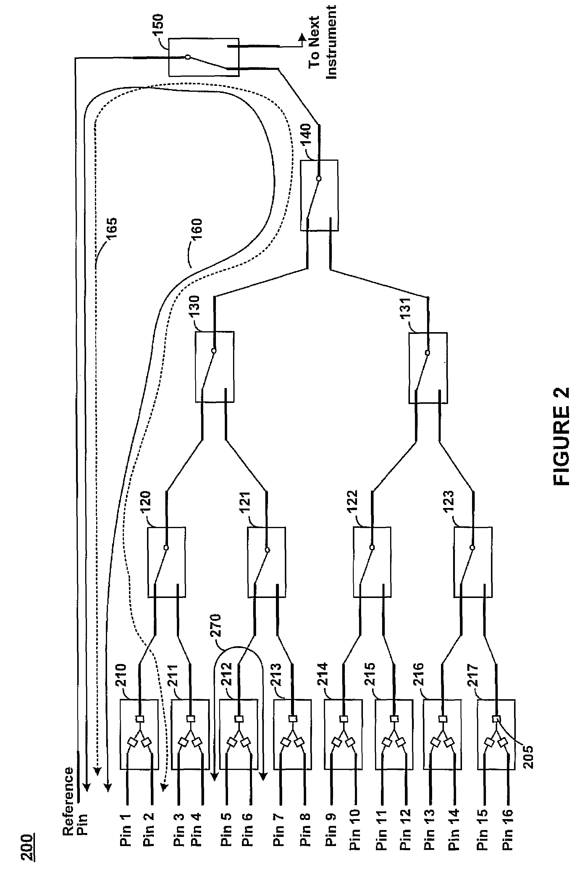
[0008]Embodiments of the present invention are directed towards an enhanced loadboard and method for enhanced automated test equipment (ATE) signaling. More specifically, embodiments provide an effective mechanism for reducing signal degradation and error interjection by replacing one or more relays with signal splitters for directing signals between one or more pins of a coupled ATE instrument, where the signal splitters reduce loadboard size and operating cost.

Problems solved by technology

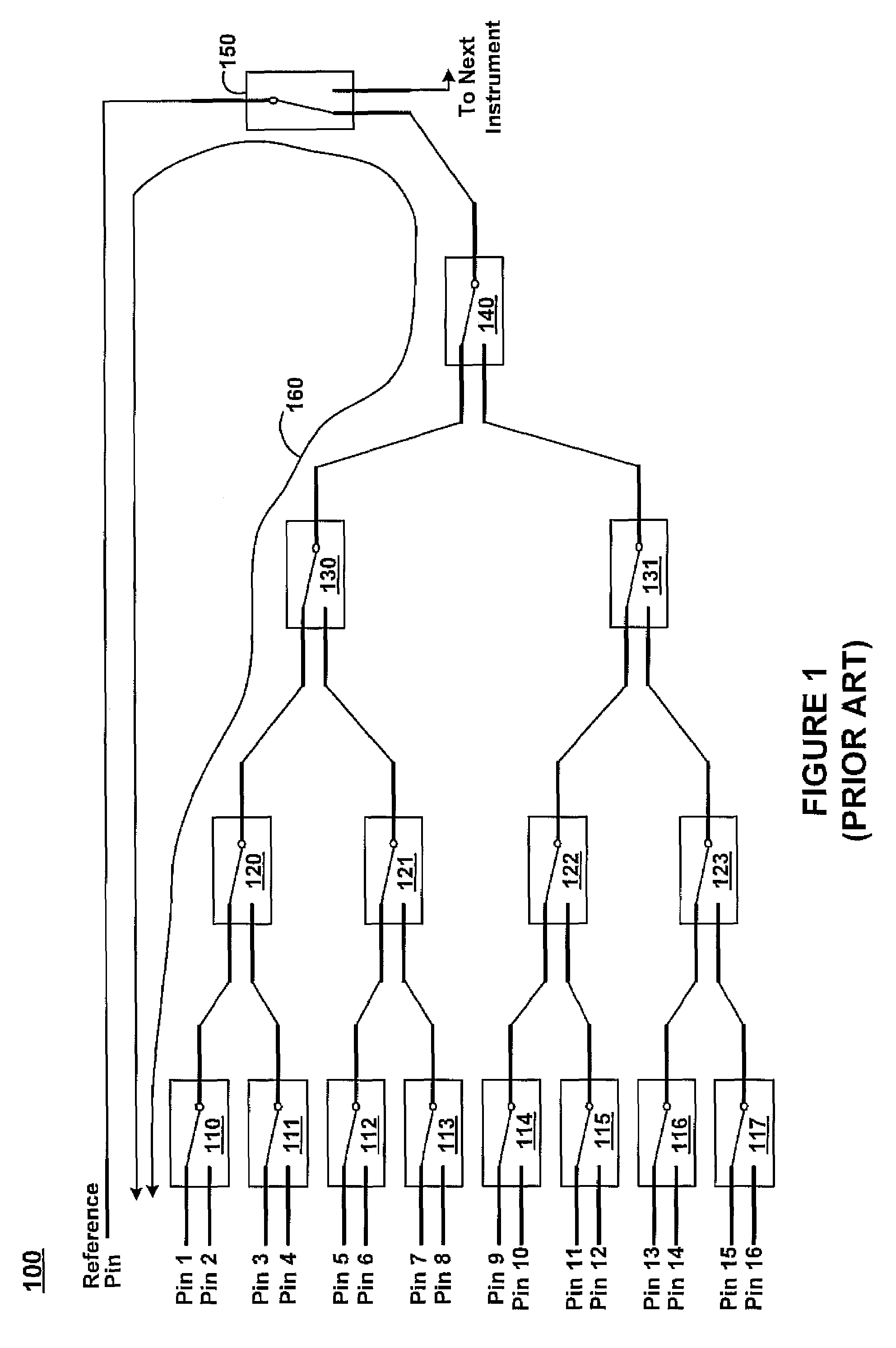
Although loadboards similar to conventional loadboard 100 have been used in the past, the increased signaling speeds used by modern DUTs are beginning to exceed the capabilities of the relays.
For example, signal degradation is common when using the relays to gate high-speed signals.
Additionally, as the average number of devices tested by ATE increases, the space and power consumption of the relays present fiscal and other logistics issues for ATE manufacturers and users alike.
Moreover, as the number of pins of an average DUT increases, the limited loadboard real estate is quickly used up, resulting in component placement which compromises signal integrity and other loadboard functionality.
As such, the need to switch relay state prevents parallel calibration, thereby increasing calibration time and cost.
In addition to adding an extra step, such comparison is likely to interject error due to hysteresis, tolerance buildup, or the like.
Thus, not only do relays affect the accuracy and precision of calibration measurements given the inherent signal degradation associated with the relays, but the need to compare measurements with respect to a functional pin exacerbates the problem by interjecting additional error.
Furthermore, the decreased accuracy and precision also bring with them increased operation cost, ATE size and signal degradation given the switched nature, large size and power consumption of the relays.

Method used


Image

  • Loadboard enhancements for automated test equipment
  • Loadboard enhancements for automated test equipment
  • Loadboard enhancements for automated test equipment

Examples


Embodiment Construction

[0020]Reference will now be made in detail to embodiments of the present invention, examples of which are illustrated in the accompanying drawings. While the present invention will be discussed in conjunction with the following embodiments, it will be understood that they are not intended to limit the present invention to these embodiments alone. On the contrary, the present invention is intended to cover alternatives, modifications, and equivalents which may be included with the spirit and scope of the present invention as defined by the appended claims. Furthermore, in the following detailed description of the present invention, numerous specific details are set forth in order to provide a thorough understanding of the present invention. However, embodiments of the present invention may be practiced without these specific details. In other instances, well-known methods, procedures, components, and circuits have not been described in detail so as not to unnecessarily obscure aspect...


PUM


Abstract

An enhanced loadboard and method for enhanced automated test equipment (ATE) signaling. More specifically, embodiments provide an effective mechanism for reducing signal degradation and error interjection by replacing one or more relays with signal splitters for directing signals between one or more pins of a coupled ATE instrument, where the signal splitters reduce loadboard size and operating cost.

Description

BACKGROUND OF THE INVENTION[0001]Loadboards are often used to calibrate and perform diagnostic tests on instruments used in automated test equipment (ATE). For example, a single loadboard coupled to an instrument may couple pins of the instrument for pin-to-pin calibration and diagnostics, whereas multiple loadboards may be coupled to couple pins of multiple instruments for instrument-to-instrument calibration and diagnostics. Given that modern integrated circuits utilize high speed signaling upwards of many gigahertz, loadboard coupled to instruments testing such high-speed devices under test (DUTs) must be able to conduct the high-speed signals with minimal signal degradation such that accurate and precise calibration and / or diagnostics may be performed.[0002]FIG. 1 shows conventional ATE loadboard 100 for coupling to an instrument. As shown in FIG. 1, loadboard 100 includes a number of relays 110-150 for coupling pins 1 through 16 to the reference pin. The 16 pins couple to a 16 ...

Claims


Application Information

Patent Timeline
IPC IPC(8): G01R31/02
CPCG01R31/31926
Inventor SHIMANOUCHI, MASASHI
Owner CREDENCE SYSTEMS
Learn More