Processing digital signal

a digital signal and processing technology, applied in the field of communication, can solve the problems of inability to maximize the overall radio network capacity, the structure of the base station cannot be optimized in the cell design, etc., and achieve the effect of low traffic load

Active Publication Date: 2016-05-31
VALUE INNOVATION PARTNERS CO LTD
View PDF70 Cites 0 Cited by
  • Summary
  • Abstract
  • Description
  • Claims
  • Application Information

AI Technical Summary

Benefits of technology

[0008]In accordance with another aspect of the present invention, radio units in adjacent cells may transmit the same data signal to one user equipment located in an overlapping area each using one antenna and using the same channel when user equipment located in an overlapping service area of two adjacent cells and / or when one of the radio units has comparatively high traffic load.
[0014]The method may further include controlling the first radio unit and the second radio unit to transmit the same signal to the user equipment each using both of the first and second antennas when the first and second radio units are determined as having comparatively low traffic load.

Problems solved by technology

Such a structure of a base station has limitations to be optimized in a cell design.
Such structure may reduce dead-spaces or holes in coverage but cannot maximize overall radio network capacity.

Method used


Image

  • Processing digital signal
  • Processing digital signal
  • Processing digital signal

Examples


Embodiment Construction

[0038]Reference will now be made in detail to embodiments of the present invention, examples of which are illustrated in the accompanying drawings, wherein like reference numerals refer to like elements throughout. The embodiments are described below, in order to explain the present invention by referring to the figures.

[0039]The term “user equipment” as used herein may refer to any of a terminal, a mobile station (MS), a mobile terminal (MT), a subscriber station (SS), a portable subscriber station (PSS), and an access terminal (AT), and may include some or all of the functions thereof.

[0040]The term “base station (BS)” as used herein may refer to any of an access point (AP), a radio access station (RAS), a node B, an evolved node B (eNodeB), a base transceiver station (BTS), and a mobile multihop relay (MMR)-BS, and may include some or all of the functions thereof.

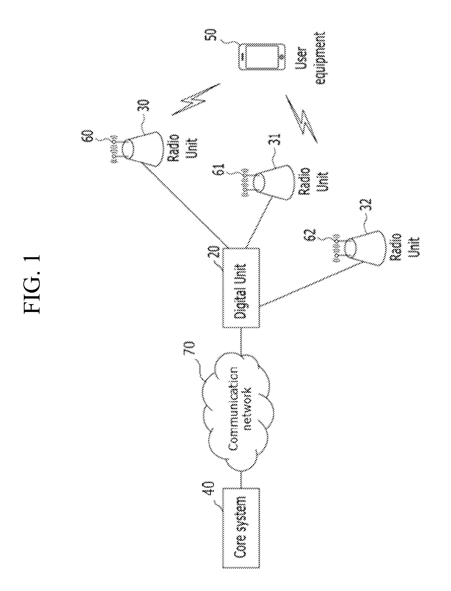
[0041]FIG. 1 shows a network in accordance with at least one embodiment of the present invention.

[0042]Referring to FI...


PUM


Abstract

Described embodiments provide a digital unit for controlling a plurality of radio units to transmit a signal to user equipment. The digital unit may determine whether user equipment is located at an overlapping service area of a first radio unit and a second radio unit and control the first radio unit to transmit a signal to the user equipment using the first antenna and control the second radio unit to transmit the same signal to the user equipment using the second antenna when the user equipment is located in the overlapping service area. A transmission pattern of the first antenna of the first radio unit may be different from a transmission pattern of the second antenna of the second radio unit.

Description

CROSS REFERENCE TO PRIOR APPLICATIONS[0001]The present application claims priority under 35 U.S.C. §119 to Korean Patent Application No. 10-2011-0142728 (filed on Dec. 26, 2011), which is hereby incorporated by reference in its entirety.[0002]The subject meter of this application is related to U.S. patent application Ser. No. 13 / 726,006 filed Dec. 22, 2012, the teachings of which are incorporated herein in their entirety by reference.FIELD OF THE INVENTION[0003]The present invention relates to communications and, in particular, to controlling radio units to transmit a signal to user equipment in an overlapping service area of the radio units.BACKGROUND OF THE INVENTION[0004]A typical base station includes a digital unit, a radio unit, and an antenna in one physical system. Such a structure of a base station has limitations to be optimized in a cell design. In order to optimize and improve the cell design, a digital unit and a radio unit are spatially separated and the radio unit is ...

Claims


Application Information

Patent Timeline
Patent Type & Authority Patents(United States)
IPC IPC(8): H04W52/24H04W52/02H04W24/08H04W76/04H04W88/08H04W88/02H04B7/02
CPCH04W52/245H04B7/022H04W24/08H04W52/0245H04W76/04H04W88/02H04W88/085Y02D30/70
Inventor LEE, KI-HOLEE, YONG-GYOOJI, YUNG-HA
Owner VALUE INNOVATION PARTNERS CO LTD
Why Eureka
Try Eureka