Motor-driven machine tool

a technology of motor-driven machine tools and power tools, which is applied in the direction of power-driven reciprocating saws, manufacturing tools, metal sawing devices, etc., can solve the problems of certain susceptibility to malfunction, limited work options, and complicated structural embodiments, and achieve the effect of simplifying the design of motor-driven power tools

Inactive Publication Date: 2016-06-07
ROBERT BOSCH GMBH
View PDF17 Cites 8 Cited by
  • Summary
  • Abstract
  • Description
  • Claims
  • Application Information

AI Technical Summary

Benefits of technology

[0006]The object of the invention is to simplify the design of a motor-driven power tool of the type mentioned at the beginning, to provide it with a rugged embodiment, and in particular to also embody it so as to enable, as needed, an orbital reciprocation mode when the working plane of the working tool is rotated relative to the longitudinal axis out of its straight-ahead working direction, i.e. a “scrolling” working mode.
[0007]The starting point for the invention is the fact that the lifting rod and the supporting element are combined by means of a supporting frame to form a unit that is supported on the housing and is able to rotate around the longitudinal axis of the working tool, permitting the supporting element to maintain its position supporting the working tool in the working plane in all rotation positions of the working tool so that the support of the working tool by the supporting element is independent of the rotation position. It is thus possible to simplify the guidance for the lifting rod and to embody this guidance in the form of a sliding guide extending in the reciprocation direction, which is in turn supported on the supporting frame by means of a pivot axle extending transversely to the working plane.
[0008]If this support on the supporting frame is provided in the frame's end region oriented away from the working tool, it is then possible for the lifting rod, starting from the working tool or the holder for the working tool and extending through the support including the sliding guide, to be embodied as rigid and for the drive connection to the reciprocating drive to be integrated into the lifting rod close to the support, which results in a very compact design and also results in only small pivoting distances, particularly in the region of the drive connection to the reciprocating drive, when the working tool is being driven in orbital mode in the direction of the working plane, thus simplifying the embodiment of the drive connection.
[0011]Preferably, the slotted crank element of the lifting rod is of one piece with the part of the lifting rod that is guided in the sliding guide in a rotationally fixed fashion in the direction of the longitudinal axis so that this part of the lifting rod can preferably be composed of flat stock, preferably embodied in the form of a stamped part. With a rigid attachment to the slotted crank element, the lifting rod, in its section extending from the slotted crank element to the tool holder, is suitably composed of round stock, in particular a rod-shaped round stock, making it possible to work with conventional tool holders.

Problems solved by technology

This results in a complicated structural embodiment and is accompanied by a certain susceptibility to malfunction, particularly under difficult working conditions.
In addition, work options are partially limited because when the working tool is rotated around its longitudinal axis relative to the straight-ahead working direction, operating the power tool in orbital reciprocation mode is only possible at best to a limited degree.

Method used


Image

  • Motor-driven machine tool
  • Motor-driven machine tool
  • Motor-driven machine tool

Examples


Embodiment Construction

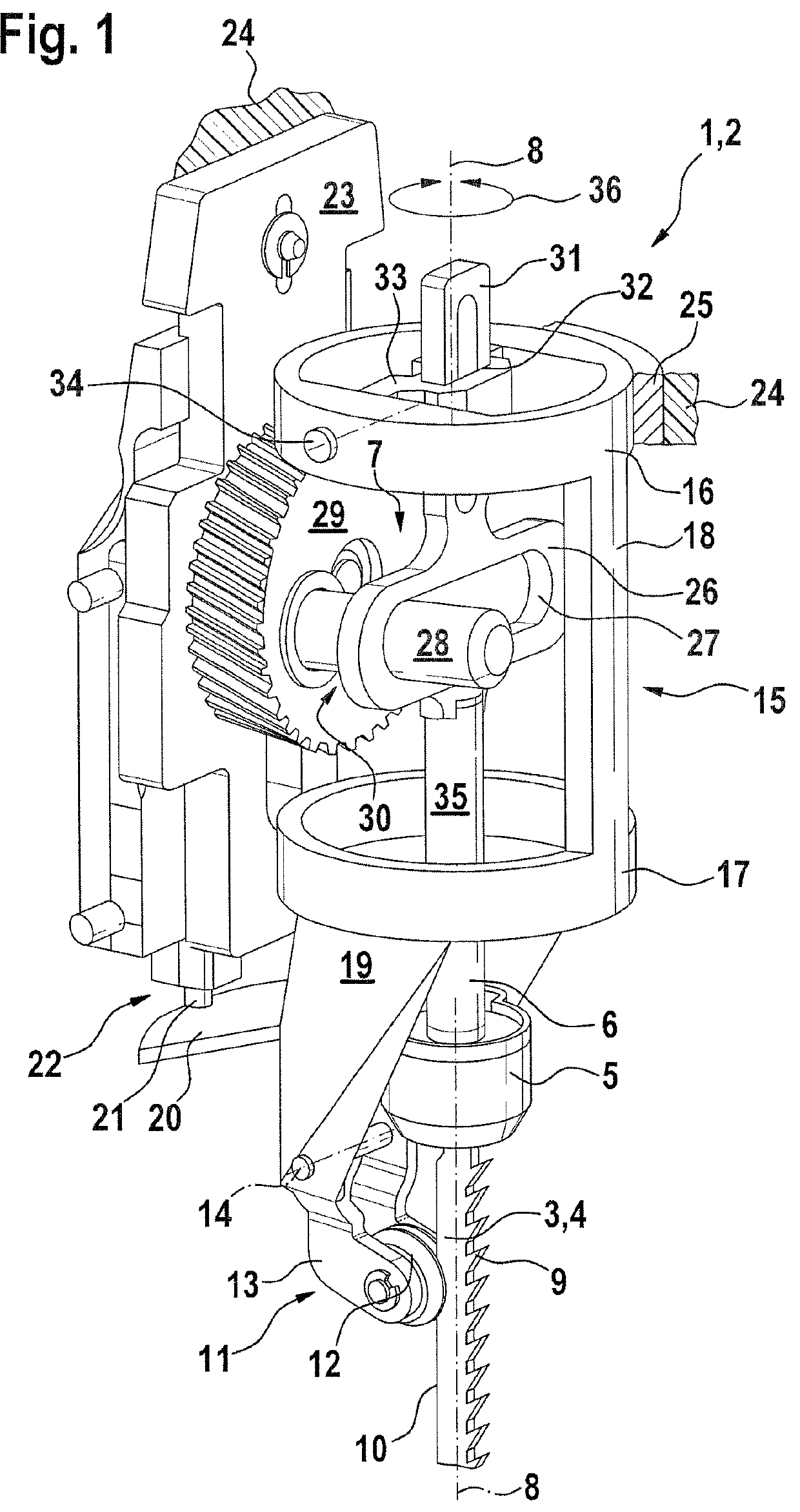
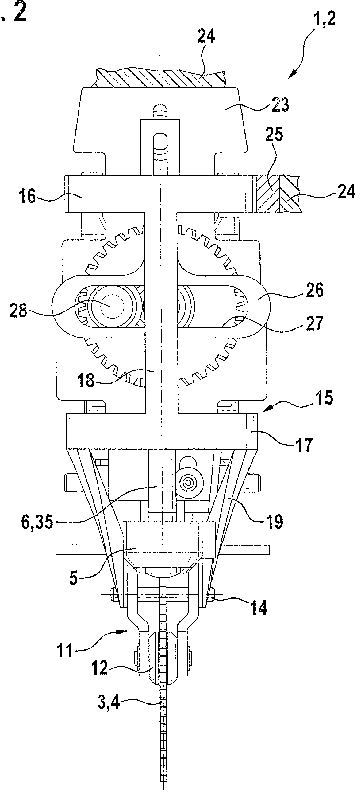
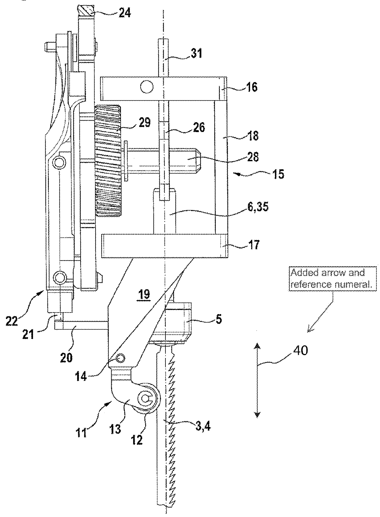
[0019]The power tool 1 shown in the figures is embodied in the form of a jigsaw 2 whose working tool 3 is constituted by a saw blade 4 that is driven to execute a reciprocating motion along a direction of axial movement 40 defined by an longitudinal axis 8 of the working tool 3. The saw blade 4 is attached via a saw blade holder 5 to a lifting rod 6 that is acted on by a reciprocating drive 7.

[0020]The saw blade 4 provided as the working tool 3 has a longitudinal axis 8 lying in the working plane of the saw blade 4, which has a set of teeth 9 in front and whose opposing saw blade spine 10 is supported against a supporting element 11 by means of a supporting roller 12. The supporting element 11 is embodied in the form of a pivot lever 13, which is linked to a supporting frame 15 by means of a pivot axle 14. With a cage-like embodiment, the supporting frame 15 has a support ring 16, which is situated at the upper end in the drawing and oriented away from the working tool 3, and has a ...


PUM

PropertyMeasurementUnit
frictionaaaaaaaaaa
axial movementaaaaaaaaaa
lengthaaaaaaaaaa

Abstract

For a machine tool designed in particular as a saber saw, a configuration including a carrying frame is provided, via which the lifting rod and the support element are joined to form a unit that can be rotated about the longitudinal axis of the power tool, is mounted on the casing side, and guides a drive part of the lift drive on the lifting rod side.

Description

CROSS-REFERENCE TO RELATED APPLICATION[0001]This application is a 35 USC 371 application of PCT / EP 2009 / 065309 filed on Nov. 17, 2009.BACKGROUND OF THE INVENTION[0002]1 Field of the Invention[0003]The invention relates to a motor-driven power tool.[0004]2 Description of the Prior Art[0005]Motor-driven power tools of the above-mentioned type are known from DE 37 02 670 A1 and are complex in design. This results in a complicated structural embodiment and is accompanied by a certain susceptibility to malfunction, particularly under difficult working conditions. In addition, work options are partially limited because when the working tool is rotated around its longitudinal axis relative to the straight-ahead working direction, operating the power tool in orbital reciprocation mode is only possible at best to a limited degree.OBJECT AND SUMMARY OF THE INVENTION[0006]The object of the invention is to simplify the design of a motor-driven power tool of the type mentioned at the beginning, ...

Claims


Application Information

Patent Timeline
Patent Type & Authority Patents(United States)
IPC IPC(8): B23D49/16B23D51/02
CPCB23D49/165B23D49/167B23D51/02
Inventor BANTLE, FLORIANKAISER, HANSKOEDER, THILOPLATZER, JOACHIMHOFFMANN, ULLIKOEGEL, JANCASOTA, MARCEL
Owner ROBERT BOSCH GMBH
Why Eureka
Try Eureka