Valve having at least one hourglass studs for coupling to diaphragm and compressor/spindle components

a diaphragm valve and hourglass stud technology, which is applied in the direction of diaphragm valves, valve arrangements, engine diaphragms, etc., can solve the problems of insufficient sealing force, inability to seal, and inability to provide sufficient sealing force, so as to eliminate the variation in the “turn” of the threaded design of the customer’s attachment. , the effect of cost saving

Active Publication Date: 2016-06-14
ITT MFG ENTERPRISES LLC
View PDF38 Cites 6 Cited by
  • Summary
  • Abstract
  • Description
  • Claims
  • Application Information

AI Technical Summary

Problems solved by technology

Some disadvantages of the threaded connection technique shown in FIGS. 1A-1D include at least the following:1. When creating the diaphragm, the metal stud is embedded in the plastic or rubber.
It is difficult to seal the threads during the high pressure processing.
This is often a separate encapsulated or pinned part, that must be constrained for rotation, but has limited freedom to travel up and down.3. It takes multiple turns for the installation and removal of the diaphragm.4. If the diaphragm is threaded too tightly, the center is pulled up away from the metal sealing surface, and the seal is defeated.
If the threads are not fully engaged, the center of the diaphragm makes hard contact with the metal sealing surface, and sufficient sealing force is not provided to the sides of the seal, allowing for leakage across the valve seal.
Worse yet, this concentrated loading can crack the diaphragm and allow fluid leakage into the bonnet.
Some disadvantages of the stud with shear pin technique shown in FIGS. 2A-2E include at least the following:1. The shear pin is an added part and process, required for each diaphragm.2. The shear pin can become dislodged or lost.3. The cross hole within the stud reduces the cross sectional area and creates a stress concentration, requiring a larger diameter stud for a given load and material.
If improperly designed, there is a possibility of tensile failure or shear pin failure.
B) The stud with shear-pin:1) Added part and assembly;2) Dislodge position or loss of pin; and3) Risk of stud tensile or shear pin failure
C) 2 piece stud:1) Additional part and labor;2) Poor reliability; and3) Alternate attachment methods are costly or unreliable.

Method used


Image

  • Valve having at least one hourglass studs for coupling to diaphragm and compressor/spindle components
  • Valve having at least one hourglass studs for coupling to diaphragm and compressor/spindle components
  • Valve having at least one hourglass studs for coupling to diaphragm and compressor/spindle components

Examples


Embodiment Construction

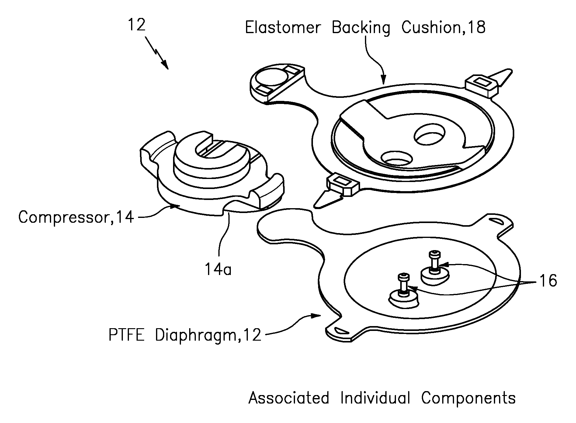
[0068]Consistent with that shown in FIGS. 5-7, the present invention may take the form of apparatus generally indicated as 10, 10′ featuring a combination of a diaphragm 12, 12′; a compressor or spindle component 14, 14′; and at least one hourglass-stud 16, 16′ having a head 16a, 16a′ configured to couple to the compressor or spindle component 14, 14′, having a lower shaft 16b configured to couple to the diaphragm 12, 12′, and having an upper shaft 16c configured to couple together the head 16a, 16a′ and the lower shaft 16b. The head 16a, 16a′ may include opposing curved surfaces 16a1, 16a1′, 16a2′ configured dimensioned with a width d1 so as to be substantially the same as the diameter d1 of the lower shaft 16b. The upper shaft 16c has a diameter d2 configured and dimensioned so as to be smaller, including slightly smaller, than the width d1 of the opposing curved surfaces 16a1, 16a1′, 16a2′ of the head 16a, 16a′.

[0069]In the embodiment disclosed in relation to FIGS. 5A and 6, the...


PUM


Abstract

Apparatus, including or forming part of a diaphragm valve, features a diaphragm; a compressor or spindle component; and at least one hourglass-stud having a head configured to couple to the compressor or spindle component, having a lower shaft configured to couple to the diaphragm, and having an upper shaft configured to couple together the head and the lower shaft, the head having opposing curved surfaces configured and dimensioned with a width so as to be substantially the same as the diameter of the lower shaft, the upper shaft having a diameter configured and dimensioned so as to be smaller, including slightly smaller, than the width of the opposing curved surfaces of the head.

Description

BACKGROUND OF THE INVENTION[0001]1. Field of the Invention[0002]The present invention relates to a diaphragm valve; and more particularly relates to a weir-type diaphragm valve.[0003]2. Brief Description of Related Art[0004]Diaphragms used within diaphragm valves are typically made from plastic or rubber, which is molded or pressed, with a metal stud in the center. The metal stud is used to move the diaphragm membrane against or away from a sealing wall within a diaphragm valve.FIGS. 1A-1DThreaded Connection[0005]Most often the stud is threaded, and is received by a female thread attached either directly or indirectly to the to the valve spindle. See also that shown in FIGS. 3A-3C.[0006]Some disadvantages of the threaded connection technique shown in FIGS. 1A-1D include at least the following:[0007]1. When creating the diaphragm, the metal stud is embedded in the plastic or rubber. It is difficult to seal the threads during the high pressure processing. In some cases, a sleeve is th...

Claims


Application Information

Patent Timeline
Patent Type & Authority Patents(United States)
IPC IPC(8): F16K7/16F16K7/12
CPCF16K7/16F16K7/126
Inventor MATALON, LOUIS E.BUTLER, RONALD G.
Owner ITT MFG ENTERPRISES LLC
Why Eureka
Try Eureka