Mechanically-Actuated Microfluidic Diaphragm Valve

a diaphragm valve and microfluidic technology, applied in the field of microfluidics technology, can solve the problems of tas device being relatively expensive, large than the actual microfluidic platform, and current 774 microfluidic devices suffering from a number of problems

Inactive Publication Date: 2009-12-24
SILVERBROOK RES PTY LTD
View PDF31 Cites 33 Cited by
  • Summary
  • Abstract
  • Description
  • Claims
  • Application Information

AI Technical Summary

Benefits of technology

[0234]deactuation of said actuator causes said finger to move towards said body, thereby closing said valve.

Problems solved by technology

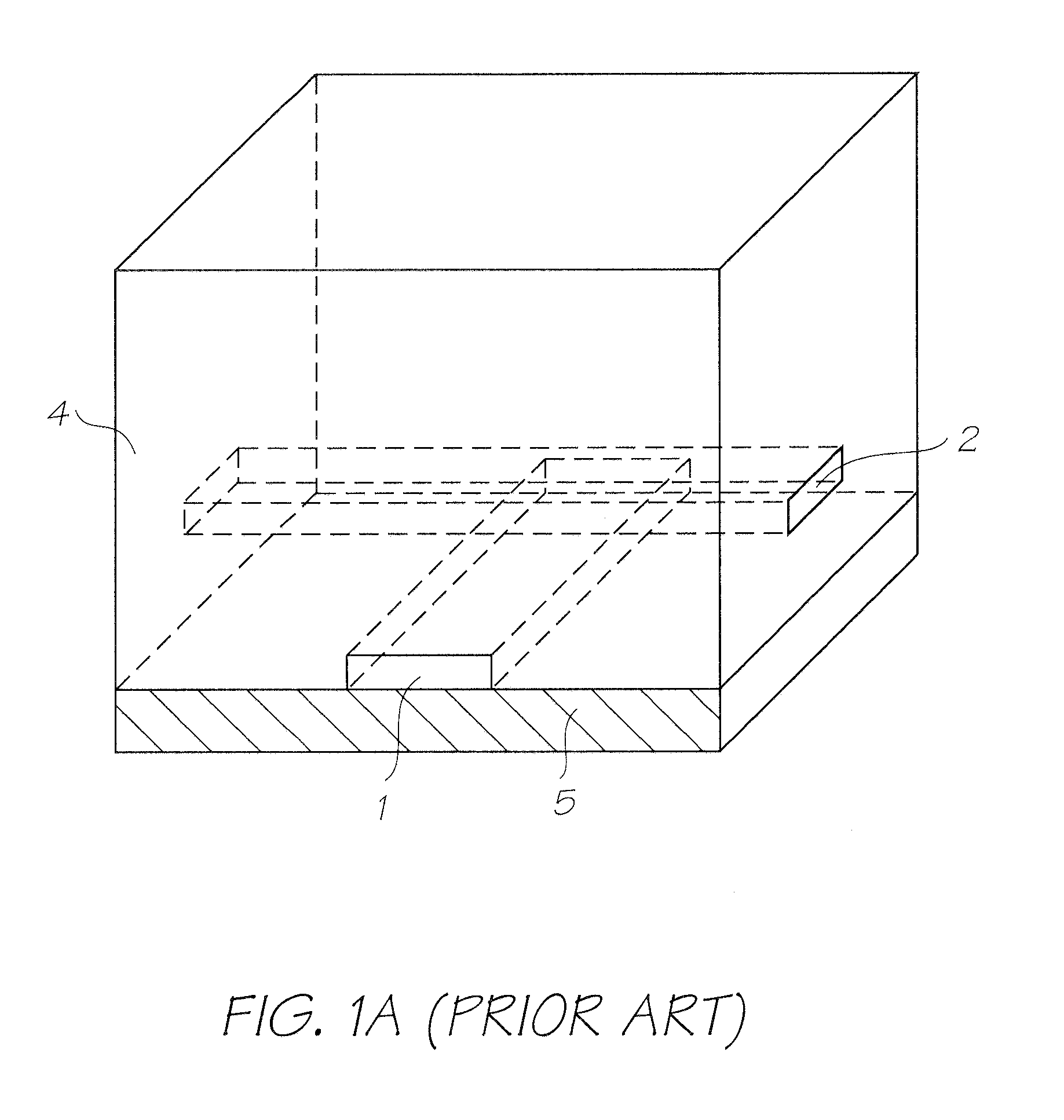
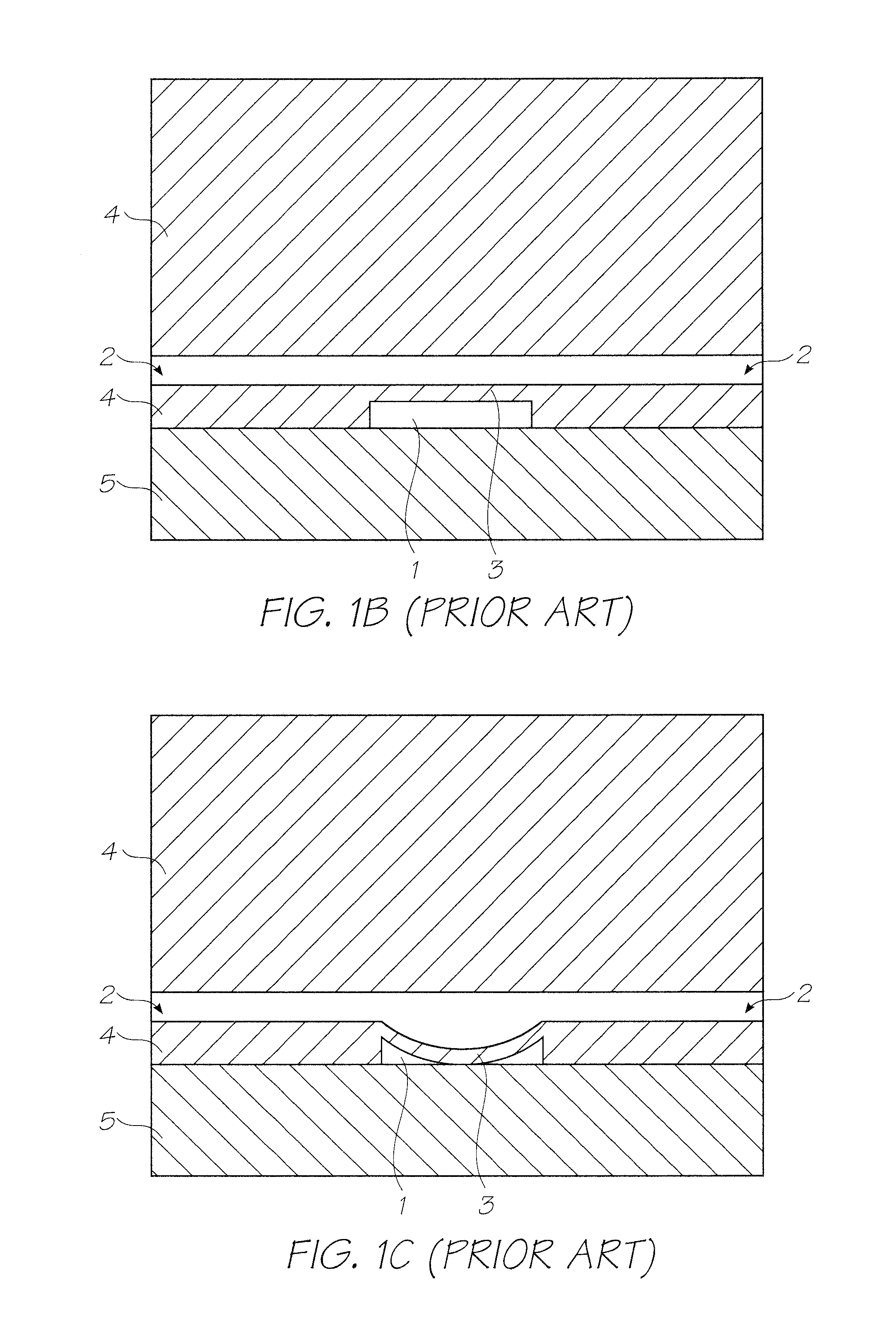
However, current microfluidics devices, such as those described in U.S. Pat. No. 7,258,774, suffer from a number of problems.
Whilst the microfluidics platform formed by soft lithography may be small and cheap to manufacture, the external support systems required to drive the microfluidics devices means that the resulting μTAS device is relatively expensive and much larger than the actual microfluidics platform.
Hence, current technology is still unable to provide fully integrated, disposable LOC or μTAS devices.

Method used


Image

  • Mechanically-Actuated Microfluidic Diaphragm Valve
  • Mechanically-Actuated Microfluidic Diaphragm Valve
  • Mechanically-Actuated Microfluidic Diaphragm Valve

Examples


Embodiment Construction

[0369]For the avoidance of doubt, the term “microfluidics”, as used herein, has its usual meaning in the art. Typically microfluidic systems or structures are constructed on a micron scale and comprise at least one microfluidic channel having a width of less than about 1000 microns. The microfluidic channels usually have a width in the range of 1-800 microns, 1-500 microns, 1-300 microns 2-250 microns, 3-150 microns or 5 to 100 microns. Microfluidic systems and devices are typically capable of handling fluidic quantities of less than about 1000 nanoliters, less than 100 nanoliters, less than 10 nanoliters, less than 1 nanoliter, less than 100 picoliters or less than 10 picoliters.

[0370]As used herein, the term “microfluidic system” refers to a single, integrated unit which is usually in the form of a ‘chip’ (in the sense that it has similar dimensions to a typical microchip). A microfluidic ‘chip’ typically has width and / or length dimensions of less than about 5 cm, less than about ...


PUM


Abstract

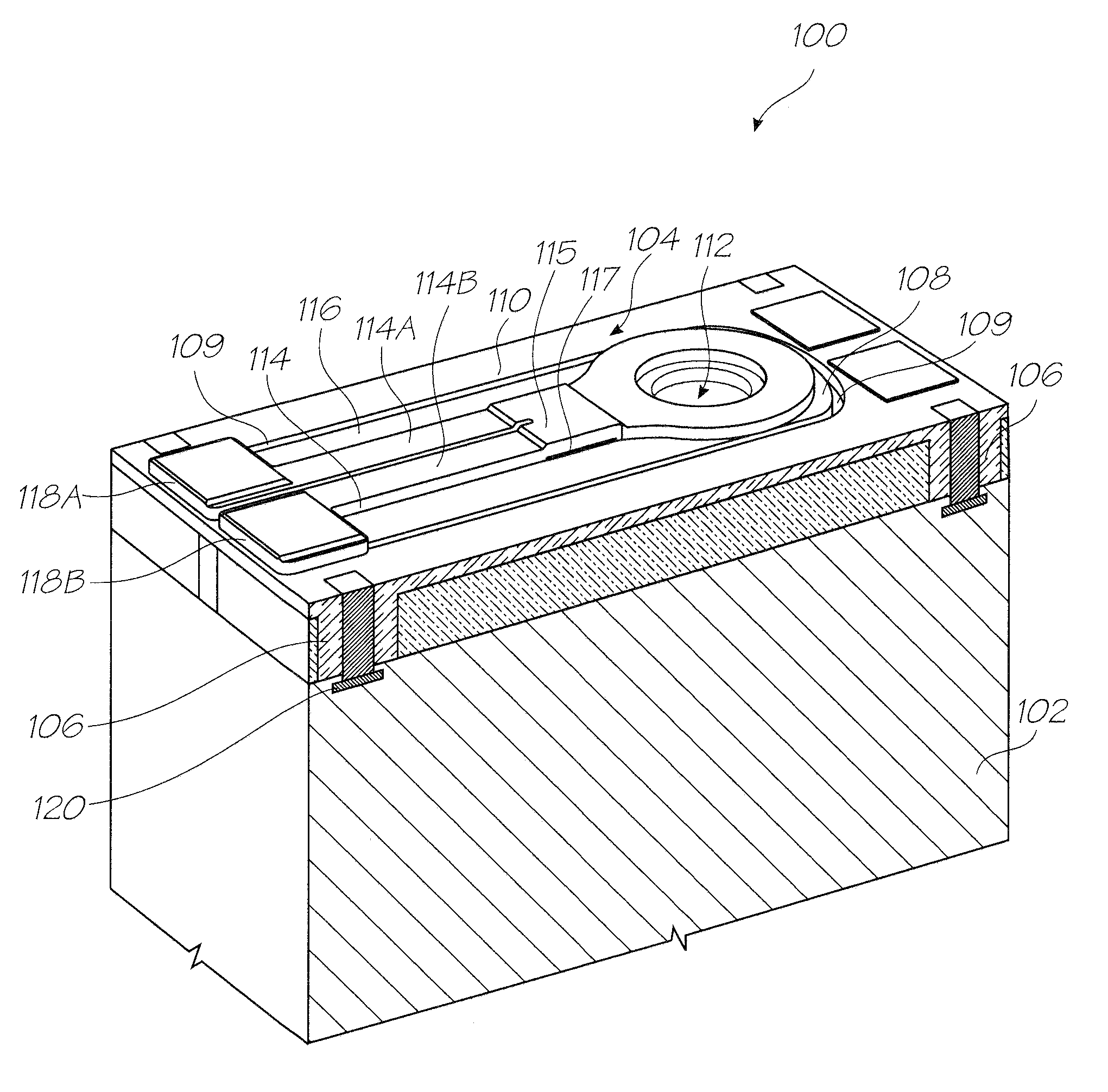
A microfluidic diaphragm valve. The valve comprises: an inlet port; an outlet port; a weir positioned between the inlet and outlet ports, the weir having a sealing surface; a diaphragm membrane for sealing engagement with the sealing surface; and a thermal bend actuator for moving the diaphragm membrane between a closed position in which the membrane is sealingly engaged with the sealing surface and an open position in which the membrane is disengaged from said sealing surface.

Description

FIELD OF THE INVENTION[0001]This invention relates to lab-on-a-chip (LOC) and microfluidics technology. It has been developed to provide fully integrated microfluidic systems (e.g LOC devices), as well as microfluidic devices which do not rely solely on soft lithographic fabrication processes.CO-PENDING APPLICATIONS [0002]The following applications have been filed by the Applicant simultaneously with the present application:LOC001USLOC002USLOC003USLOC004USLOC005USLOC006USLOC008USLOC009USLOC010USLOC011USLOC012USLOC013US[0003]The disclosures of these co-pending applications are incorporated herein by reference. The above applications have been identified by their filing docket number, which will be substituted with the corresponding application number, once assigned.CROSS REFERENCES[0004]The following patents or patent applications filed by the applicant or assignee of the present invention are hereby incorporated by cross-reference. 7344226 732897611 / 68508411 / 68508611 / 68509011 / 740925...

Claims


Application Information

Patent Timeline
Patent Type & Authority Applications(United States)
IPC IPC(8): F16K31/64
CPCB01L3/50273F16K2099/0084B01L2300/0816B01L2300/0887B01L2400/0481B01L2400/0633B01L2400/0655C08L2201/12F04B43/043F04B43/06F16K99/0001F16K99/0007F16K99/0038F16K2099/008B01L3/502738F04B43/14Y10T137/2229Y10T137/9138
Inventor MCAVOY, GREGORY JOHNKERR, EMMA ROSESILVERBROOK, KIA
Owner SILVERBROOK RES PTY LTD
Why Eureka
Try Eureka