Solenoid-actuated diaphragm valve

Inactive Publication Date: 2009-08-27
KOZAK EUGENIUSZ
View PDF22 Cites 32 Cited by
  • Summary
  • Abstract
  • Description
  • Claims
  • Application Information

AI Technical Summary

Benefits of technology

[0035]Yet a further object of the present invention is to provide a solenoid-actuated diaphragm valve in which the diaphragm can withstand high fluid pressure, and more specifically one in which the diaphragm has a rigid, acute central projection that extends into the central valve seat inlet in the closed position.
[0036]Still another object of the present invention

Problems solved by technology

In Allen, U.S. Pat. No. 4,295,631, the de-energized plunger does not push the diaphragm, but instead closes a pilot valve extending through the center of the diaphragm, thereby creating an unbalanced fluid pressure above the diaphragm which urges it against the valve seat.
There are a host of problems associated with both the “integral diaphragm” and “detached diaphragm” designs.
While Gilchrist avoids these problems, it does so at the cost of a quite constricted fluid passage through the valve seat in the open position, which will retard the fluid flow and create pressure build-upon the diaphragm.
As for the detached diaphragm designs, Allen and Sule achieve a short plunger stroke but involve considerable dead volume.
While Holtermann and Kazama achieve both a short plunger stroke and minimal dead volume, they rely critically on the alignment of the plunger with the center of the diaphragm, which is likely to deviate over time.
Moreover, repeated impact on the plunger on the center of the diaphragm will produce scoring and accelerate fatigue failure over time.
Both Holtermann and Kazama have the additional drawback of employin

Method used


Image

  • Solenoid-actuated diaphragm valve
  • Solenoid-actuated diaphragm valve
  • Solenoid-actuated diaphragm valve

Examples


Embodiment Construction

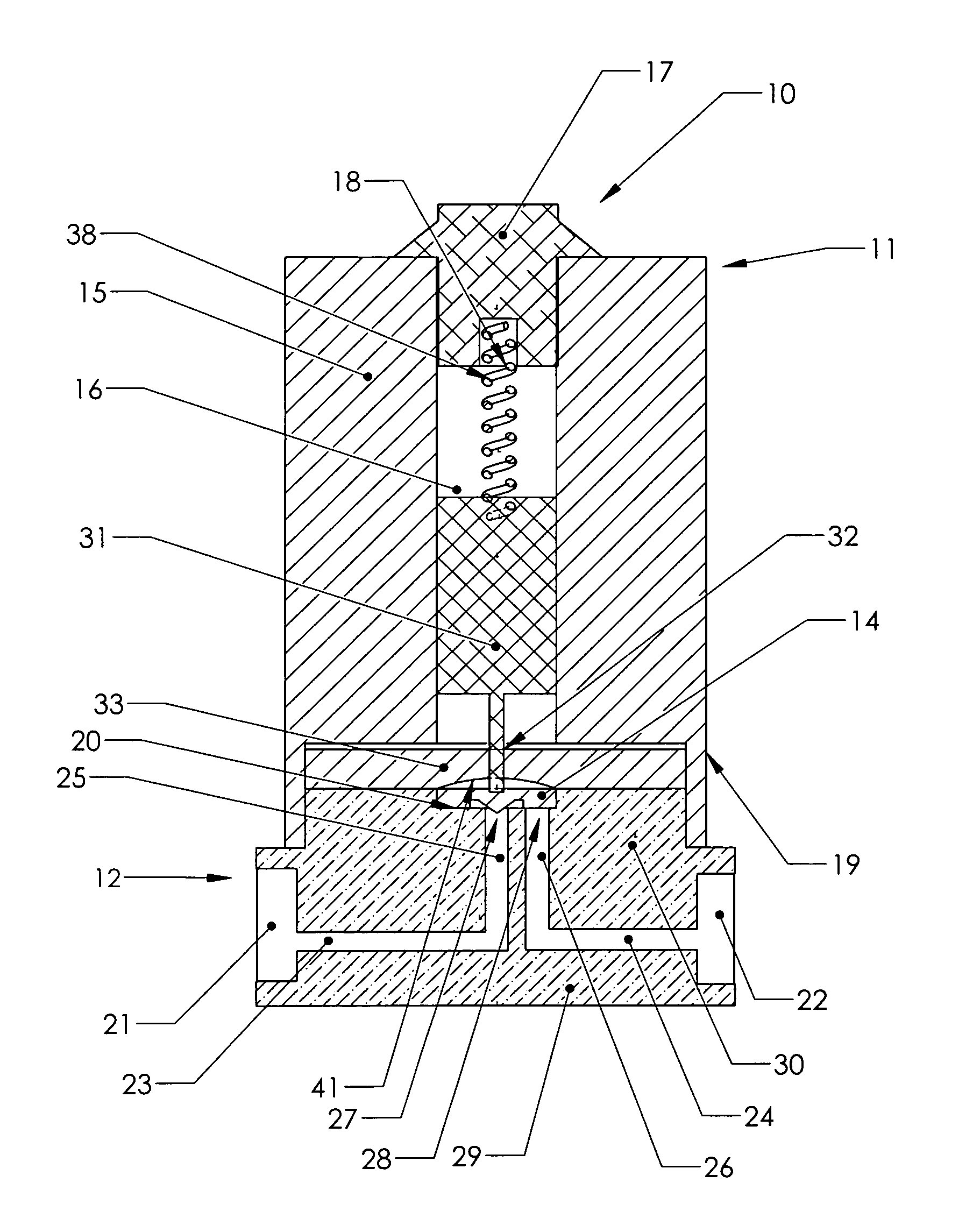
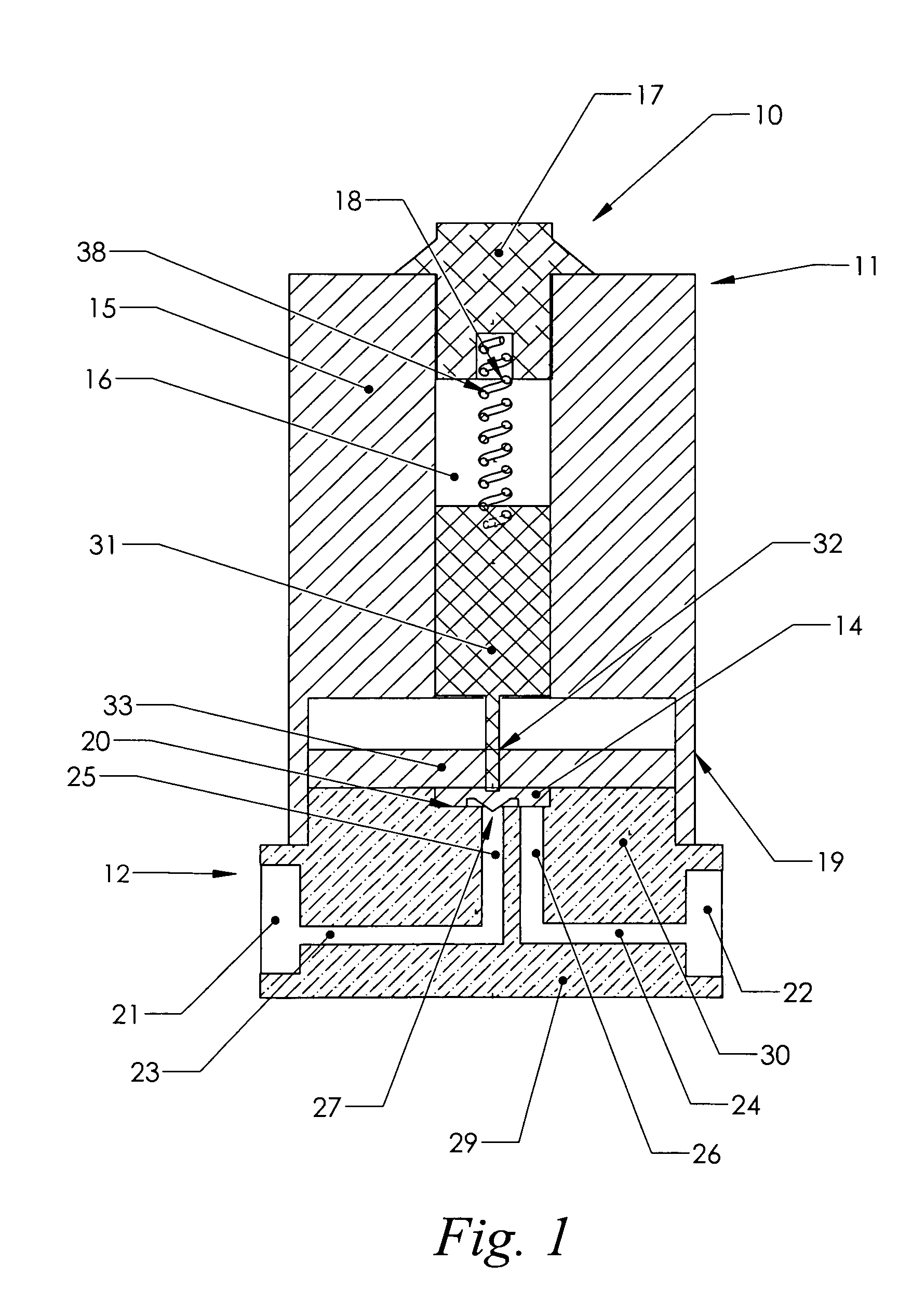
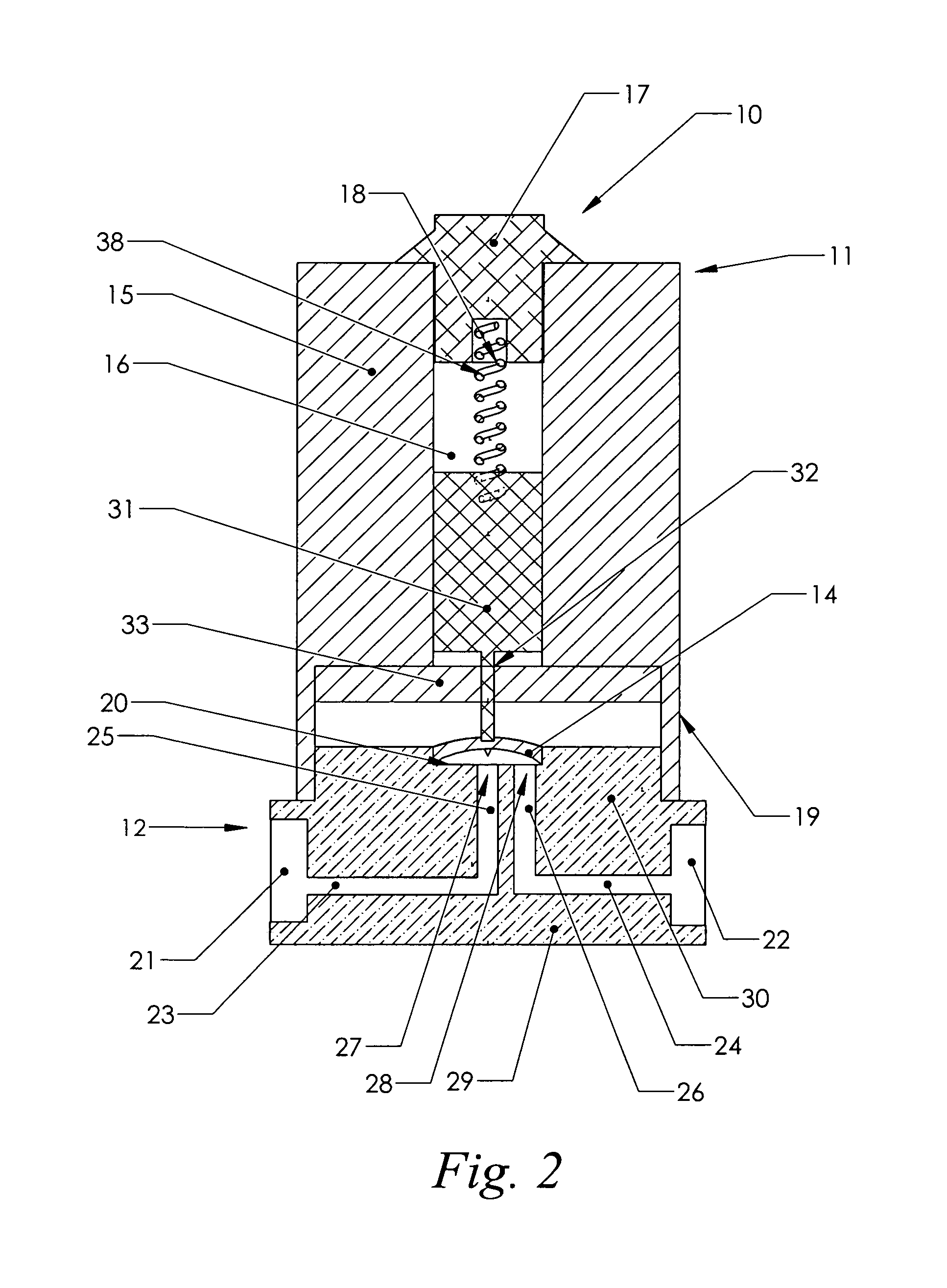
[0050]In the following detailed description of the two preferred embodiments, it should be understood that the novel features of the present invention relate to the plunger and the diaphragm, and that the other features described herein are merely typical features of a generic solenoid-actuated diaphragm valve. Therefore, the configuration of the various elements of the valve other than the plunger and the diaphragm are for illustrative and exemplary purposes only, and are not intended to limit the scope of the present invention. Thus, for example, while a specific configuration of the valve body and valve seat is described herein, this configuration can be varied to according to the desired flow pattern of the valve without impairing the utility or applicability of the present invention.

[0051]As used in the following description, the term “proximal” refers to the part of an element oriented toward the base of the valve, while the term “distal” refers to the part of an element orien...


PUM


Abstract

A solenoid-actuated diaphragm valve achieves minimal dead volume, tolerance of high pressures, prolonged diaphragm life, and energy conservation using a three-sector multi-seal diaphragm combined with a three-component plunger, which automatically switches from bilateral to unilateral circumferential diaphragm restraint between the closed and open positions.

Description

FIELD OF THE INVENTION[0001]The present invention relates to valves that control fluid flow by using a flexible diaphragm to seal one or more fluid passages, and more particularly to valves in which the sealing diaphragm is deformed through the application of a biasing force transmitted by the movement of a solenoid armature.BACKGROUND OF THE INVENTION[0002]Solenoid-actuated diaphragm valves are widely used in fluid distribution systems to control fluid flow. In isolation valves, the fluid can be isolated and channeled to designated passages and / or chambers within the valve through the displacement of a flexible diaphragm. The displacement of the diaphragm typically causes it to engage or disengage with a valve seat where two or more fluid passages terminate. Typically, in the neutral or de-energized condition, the diaphragm engages the valve seat sufficiently to seal one or more of the fluid passages, thereby interrupting or redirecting the fluid flow through the valve. The neutral...

Claims


Application Information

Patent Timeline
IPC IPC(8): F16K31/02
CPCF16K31/0672
Inventor KOZAK, EUGENIUSZ
Owner KOZAK EUGENIUSZ
Why Eureka
Try Eureka