High-speed diaphragm valve for atomic layer deposition

a diaphragm valve, high-speed technology, applied in the direction of diaphragm valves, engine diaphragms, water supply installations, etc., can solve the problems of slow valve speed increase, compress or expand gas trapped in enclosed space, etc., to reduce the efficiency of ald reactor, reduce the amount of time, and slow the movement of the diaphragm

Inactive Publication Date: 2005-09-13
BENEQ OY
View PDF32 Cites 32 Cited by
  • Summary
  • Abstract
  • Description
  • Claims
  • Application Information

AI Technical Summary

Benefits of technology

[0012]The present inventors have recognized that a conventional diaphragm valve typically encounters resistance when transitioning between the open and closed positions. Gas present in an enclosed space behind the diaphragm and adjacent an outer side of the diaphragm opposite the valve passage is typically at ambient pressure in conventional diaphragm valves. When the pressure of a medium in the valve passage is substantially lower or higher than the ambient pressure in the enclosed space, a differential pressure is exerted on the diaphragm. In some diaphragm valves, the space behind the diaphragm is tightly sealed, resulting in compression or expansion of gas trapped in the enclosed space when the diaphragm moves between the open and closed positions. Resistance caused by differential pressure and / or expansion or contraction of trapped gas can slow the movement of the diaphragm. In an ALD reactor, slow valve speed increases the amount of time it takes to pulse a quantity of precursor vapor into the reaction chamber and reduces the efficiency of the ALD reactor. Resistance can also stress the diaphragm and valve actuator.
[0013]In accordance with the present invention, a diaphragm valve includes a pressure vent communicating with the enclosed space, for reducing resistance to transitioning of the diaphragm between the open and closed positions. In some implementations, a pump or other source of suction is coupled to the pressure vent to reduce fluid pressure in the enclosed space.

Problems solved by technology

In some diaphragm valves, the space behind the diaphragm is tightly sealed, resulting in compression or expansion of gas trapped in the enclosed space when the diaphragm moves between the open and closed positions.
In an ALD reactor, slow valve speed increases the amount of time it takes to pulse a quantity of precursor vapor into the reaction chamber and reduces the efficiency of the ALD reactor.

Method used


Image

  • High-speed diaphragm valve for atomic layer deposition
  • High-speed diaphragm valve for atomic layer deposition
  • High-speed diaphragm valve for atomic layer deposition

Examples


Embodiment Construction

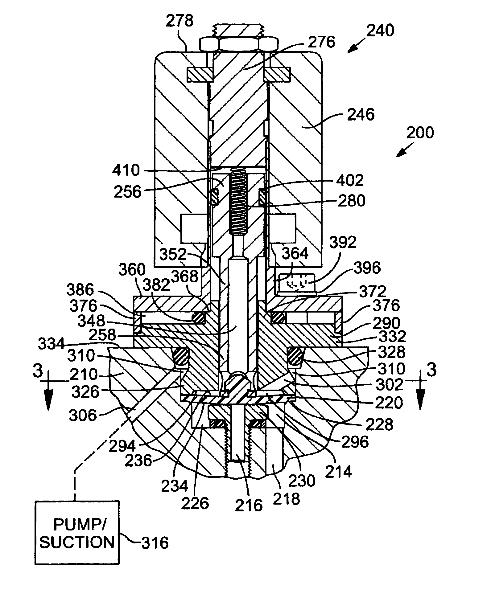
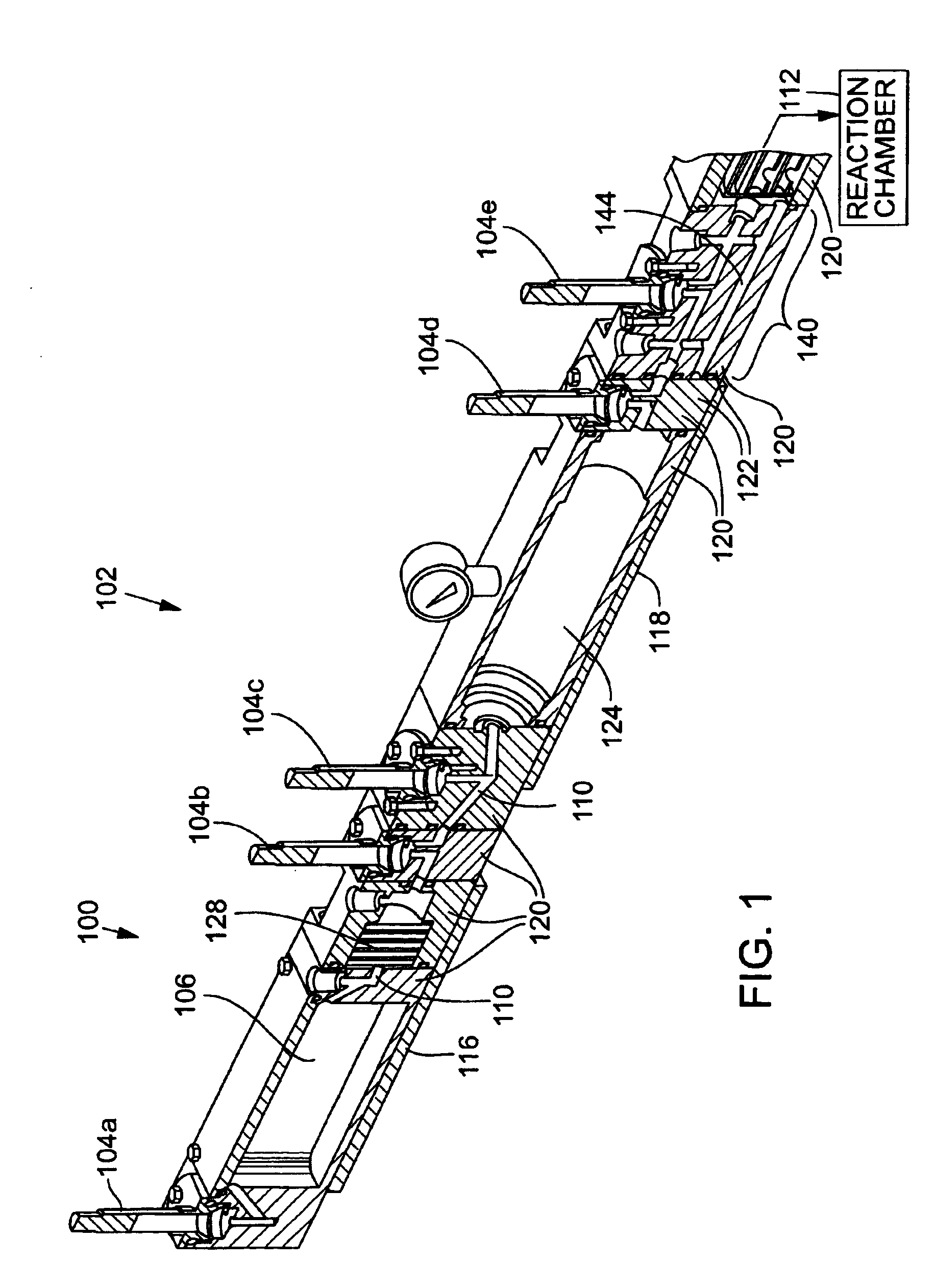
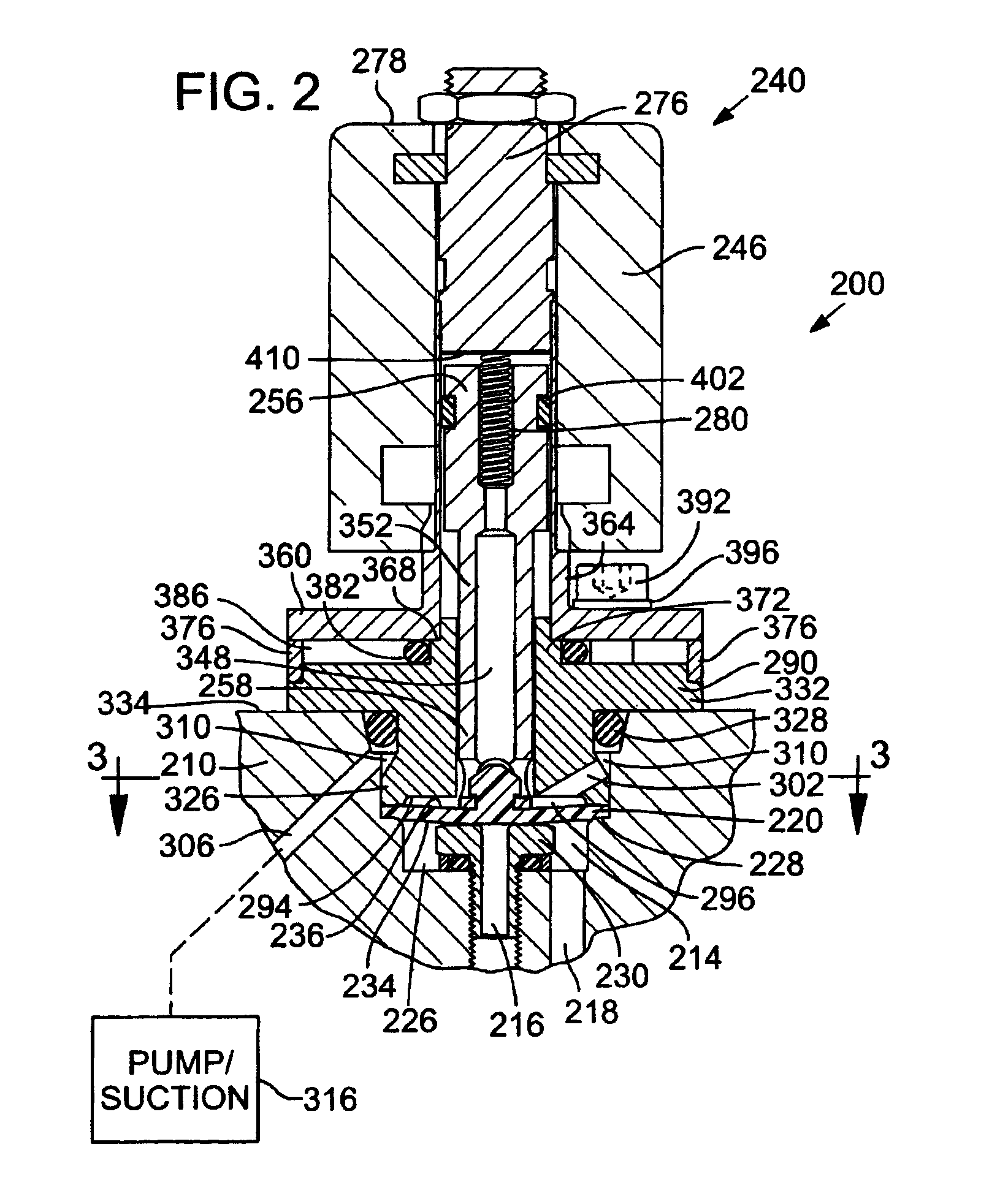
[0020]FIG. 1 is an isometric section view of a precursor material delivery system 100 of an ALD reactor 102, which comprises an exemplary environment of use for valves 104a-104e, in accordance with a first preferred embodiment. With reference to FIG. 1, a supply of precursor material is stored in a precursor container 106, where it is heated and vaporized before flowing through a flow path 110 of the precursor material delivery system 100 (generally from left to right in FIG. 1) and into a reaction chamber 112. ALD reactor 102 will typically have two or more precursor material delivery systems 100 connected to reaction chamber 112. Precursor material delivery system 100 includes electric heaters 116 and 118 for heating precursor materials in the flow path 110. Valves 104a-104e are used to control the flow of precursor material and regulate pressure of the precursor vapor at different stages in precursor material delivery system 100.

[0021]Precursor material delivery system 100 prefer...


PUM


Abstract

A diaphragm valve includes a pressure vent communicating with an enclosed space behind the diaphragm for reducing resistance to transitioning of the diaphragm between the open and closed positions. In some implementations, a pump or other source of suction is coupled to the pressure vent to reduce fluid pressure in the enclosed space. When used in an atomic layer deposition (ALD) system, the venting and suction improves the thin film deposition process and prevents leakage through the valve of potentially toxic ALD precursor vapors. Features for thermal management and reliability enhancement are also described.

Description

TECHNICAL FIELD[0001]The present invention relates to a diaphragm valve that is particularly useful in high-temperature thin film deposition systems and equipment.BACKGROUND OF THE INVENTION[0002]Atomic Layer Deposition (“ALD”), also known as Atomic Layer Epitaxy (“ALE”), is a method of depositing thin films onto a substrate that involves sequential and alternating self-saturating surface reactions. The ALD process is described in U.S. Pat. No. 4,058,430 of Suntola et al., which is incorporated herein by reference. ALD offers several benefits over other thin film deposition methods, such as Physical Vapor Deposition (“PVD”) (e.g., evaporation or sputtering) and Chemical Vapor Deposition (“CVD”), which are well known to those skilled in the art, as described in Atomic Layer Epitaxy (T. Suntola and M. Simpson, eds., Blackie and Son Ltd., Glasgow, 1990). ALD methods have been proposed for use in depositing thin films on semiconductor wafer substrates, to achieve desired step coverage a...

Claims


Application Information

Patent Timeline
Patent Type & Authority Patents(United States)
IPC IPC(8): F16K31/06F16K7/12F16K49/00F16K7/14
CPCF16K7/14F16K31/0693F16K49/002Y10T137/0318Y10T137/6416Y10T137/6606
Inventor MAULA, JARMO ILMARILESKINEN, HANNULANG, TEEMUKUOSMANEN, PEKKAHARKONEN, KARIAITCHISON, BRADLEY J.
Owner BENEQ OY
Why Eureka
Try Eureka