Throttle providing unobstructed air flow path when fully open and vortex generating configuration when partly open

a technology of vortex generation and throttle, which is applied in the direction of valve arrangement, machine/engine, plug valve, etc., can solve the problems of substantial drag and turbulence, air flow with minimal turbulence, and not providing an opening, so as to reduce the cross-sectional area, minimize turbulence, and enhance engine performance

Inactive Publication Date: 2012-11-27
CAMMARATA EDWARD
View PDF5 Cites 33 Cited by
  • Summary
  • Abstract
  • Description
  • Claims
  • Application Information

AI Technical Summary

Benefits of technology

[0022]A throttle is provided including a throttle body having a generally tubular throttle body side wall with a throttle body side wall interior surface defining a throttle body interior for containing an air flow path for delivering air into at least one cylinder of an engine; and a flow regulating mechanism including a diaphragm valve secured to the throttle body and extending diametrically across the throttle body interior for progressively reducing and progressively increasing the diameter of an air flow passing valve opening defined within the diaphragm valve, and thereby regulating air flow through the throttle body.
[0025]and an air flow regulating annular diaphragm valve including a number of valve blades mounted to converge radially toward and retract from the center of the air passageway to provide a valve opening of selectively increasing or decreasing cross-sectional area, the opening being concentric with the throttle body air passageway and substantially symmetrical, thereby regulating air flow while minimizing turbulence.
[0026]The blades preferably are configured and mounted so that as they converge to close the air passageway, throughout their intermediate positions between fully open and fully closed, they define a substantially star-shaped opening, wherein the arms of the star shape are uniformly arched along their lengths in one of a clockwise direction and a counter-clockwise direction; so that the blades are believed to cause air passing through the partially open valve to swirl and define a vortex for enhanced engine performance. The valve blades preferably retract radially entirely out of the air flow passageway when the valve is fully open. The mounting recess preferably is a stepped jog in the throttle body side wall interior surface.

Problems solved by technology

A problem with these prior throttle bodies has been that the butterfly valve extends through the middle of the flow path and significantly obstructs air flow even when the valve is fully open, causing substantial drag and turbulence.
Should such a valve have been provided, it could not provide an opening which is in all positions generally circular or symmetrical, or one which is continually centered within the air flow path.
As a result, air flow with minimized turbulence and drag is not provided.

Method used


Image

  • Throttle providing unobstructed air flow path when fully open and vortex generating configuration when partly open
  • Throttle providing unobstructed air flow path when fully open and vortex generating configuration when partly open
  • Throttle providing unobstructed air flow path when fully open and vortex generating configuration when partly open

Examples


first preferred embodiment

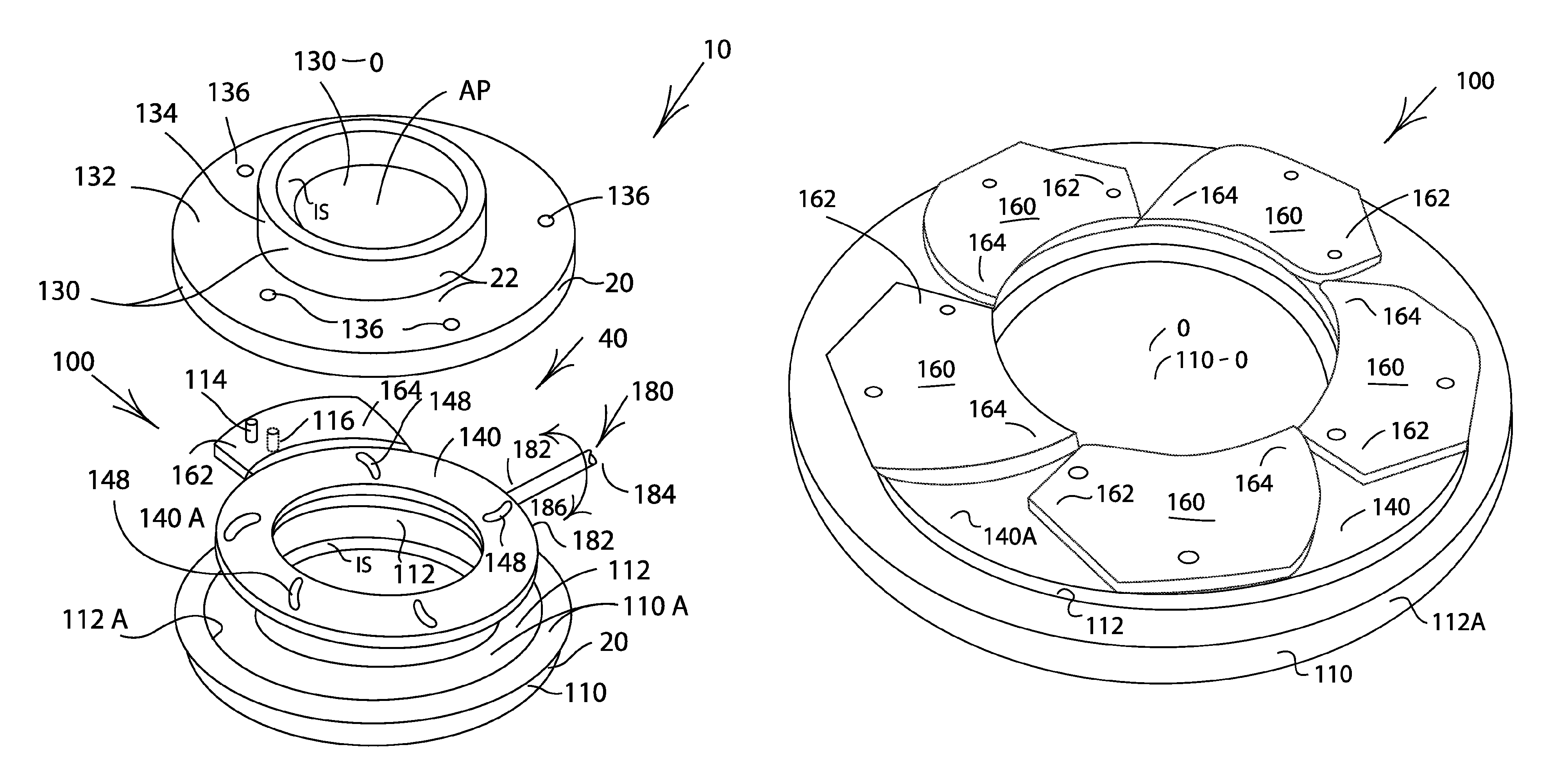
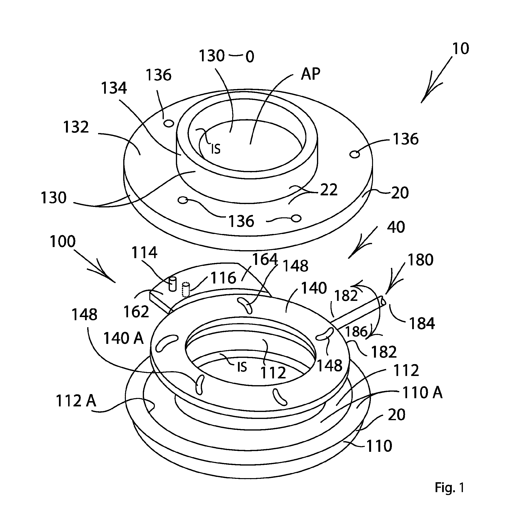
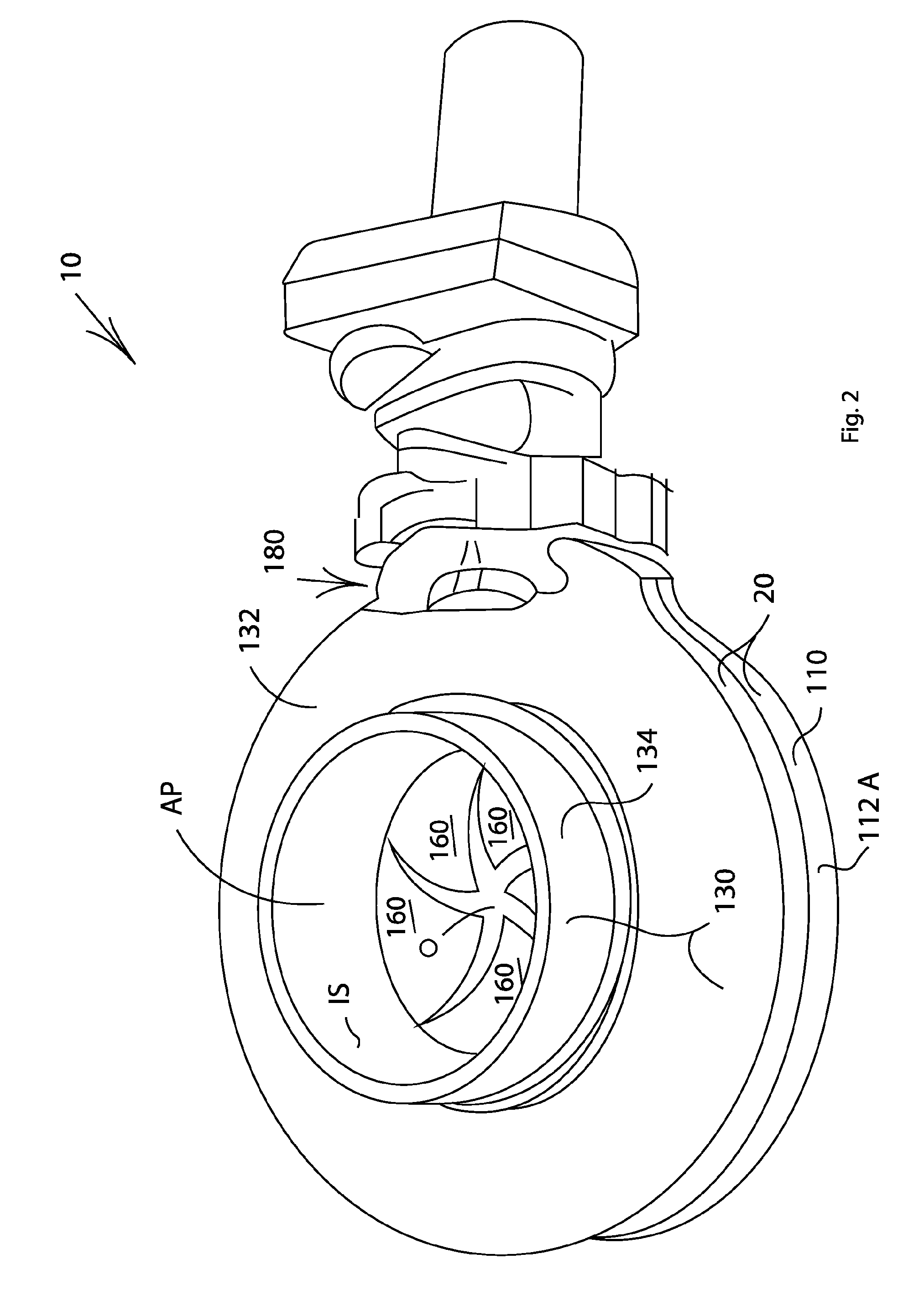
[0041]Referring to FIGS. 1-10, a throttle 10 having a throttle body 20 with a tubular throttle body side wall 22 defining a throttle body air passageway AP for containing an air flow path delivering air into at least one internal combustion engine cylinder (not shown), and a flow regulating mechanism 40 comprising an annular diaphragm valve 100 including thick valve blades 160 or plates which retract fully out of the air passageway AP and are co-planar, and which provide a valve opening O of selectively increasing or decreasing cross-sectional area, the opening being concentric with the throttle body air passageway AP and substantially symmetrical, thereby regulating air flow while minimizing turbulence.

[0042]The blades 160 are configured and mounted so that as they converge to close the throttle 10, throughout their intermediate positions between fully open and fully closed, they define a substantially star-shaped opening. The arms of the star shape are uniformly arched along their...


PUM


Abstract

A throttle includes a throttle body having a generally tubular throttle body side wall with a throttle body side wall interior surface defining a throttle body interior for containing an air flow path for delivering air into at least one cylinder of an engine; and a flow regulating mechanism including an diaphragm valve secured to the throttle body and extending diametrically across the throttle body interior for progressively reducing and progressively increasing the diameter of an air flow passing valve opening defined within the diaphragm valve, and thereby regulating air flow through the throttle body.

Description

FILING HISTORY[0001]This application is a continuation-in-part of application Ser. No. 12 / 927,087, filed on Nov. 5, 2010.BACKGROUND OF THE INVENTION[0002]1. Field of the Invention[0003]The present invention relates generally to the field of internal combustion engines and engine parts. More specifically the present invention relates to a throttle having a throttle body with a tubular throttle body side wall defining a throttle body air passageway for containing an air flow path delivering air into at least one internal combustion engine cylinder, and a flow regulating mechanism comprising an annular diaphragm valve similar in configuration to an iris diaphragm camera shutter and including thick valve blades or plates fitted into a circumferential mounting recess in the throttle body side wall interior surface to be co-planar and providing a valve opening of selectively increasing or decreasing cross-sectional area, the opening being concentric with the throttle body air passageway a...

Claims


Application Information

Patent Timeline
Patent Type & Authority Patents(United States)
IPC IPC(8): F02D9/08F16K5/08
CPCF16K3/03F02D9/12
Inventor CAMMARATA, EDWARD
Owner CAMMARATA EDWARD
Why Eureka
Try Eureka