
Flow compensated control valve

a control valve and flow compensation technology, applied in the direction of diaphragm valves, engines, instruments, etc., can solve the problems of reducing the supply of cold during the shower, inability to maintain a constant temperature of the shower, and many experiencing the unpleasant effects of momentarily being sprayed

Inactive Publication Date: 2005-11-24
MASCO CORP
View PDF12 Cites 33 Cited by
  • Summary
  • Abstract
  • Description
  • Claims
  • Application Information

AI Technical Summary

Benefits of technology

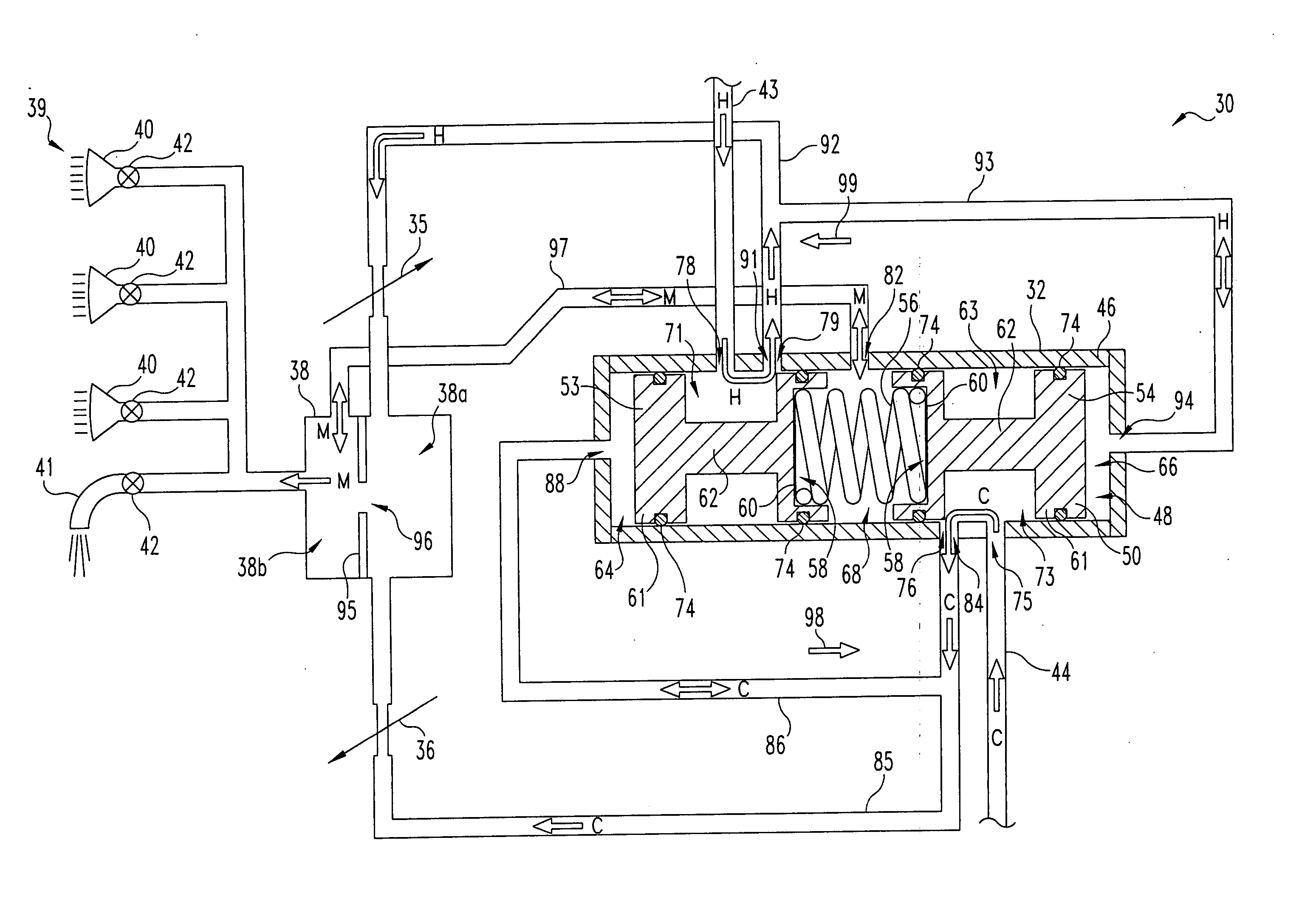
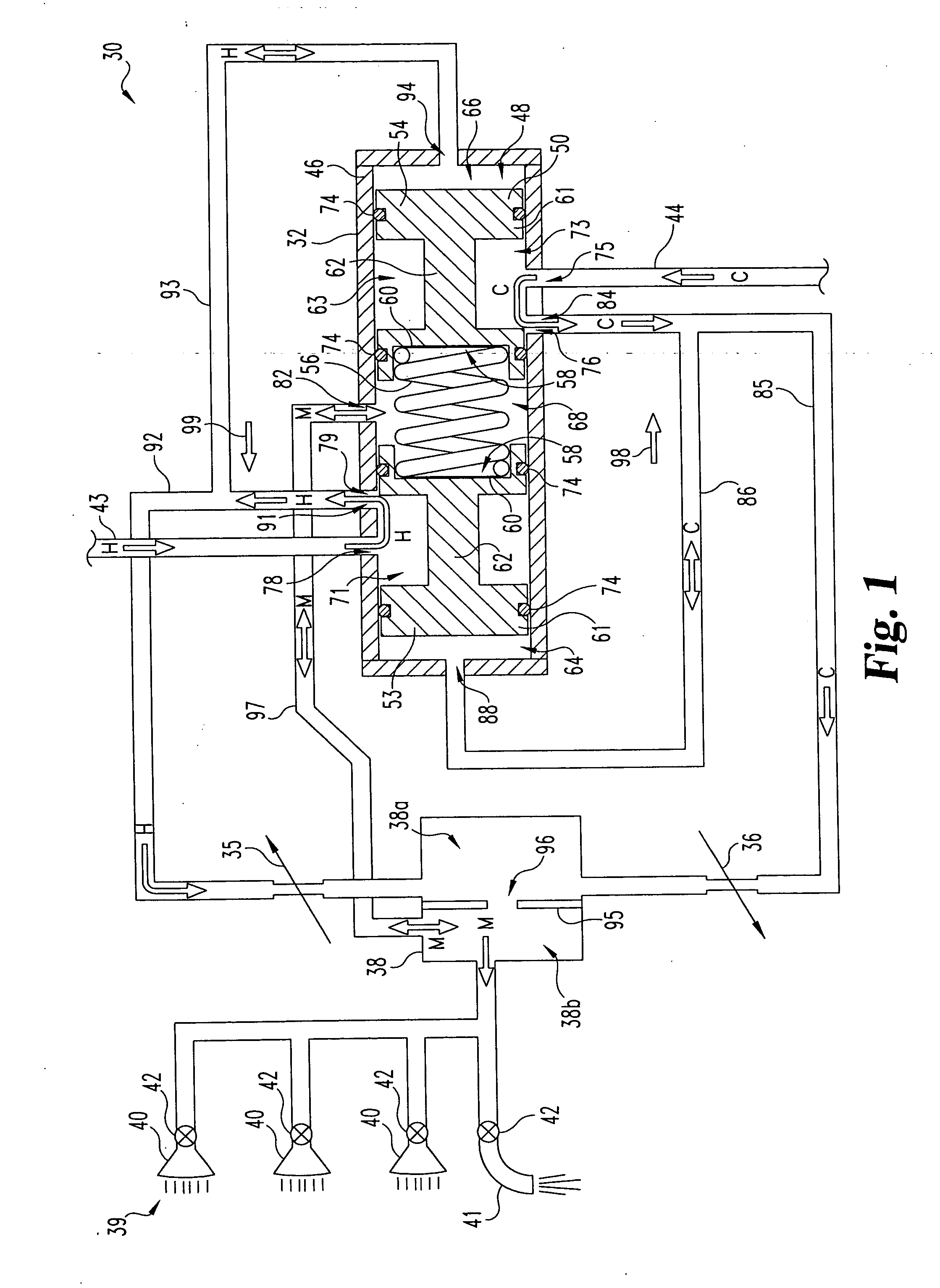
[0004] One aspect of the present invention concerns a fluid control valve system. The system includes a flow sensor configured to sense flow of a mixed fluid that includes at least a first fluid and a second fluid. The system further includes a valve. The valve includes a flow regulator operatively coupled to the flow sensor to regulate the flow of the mixed fluid based on the flow of the mixed fluid sensed by the flow sensor. The flow regulator defines at least in part a first flow opening through which the first fluid flows. The flow regulator is configured to shrink the first flow opening to reduce flow of the first fluid upon a decrease in the flow of the mixed fluid at the flow sensor and to enlarge the first flow opening to increase flow of the first fluid upon an increase in the flow of the mixed fluid at the flow sensor. A mixture regulator defines at least in part the first flow opening, and the mixture regulator is configured to regulate a mixture ratio of the first fluid and the second fluid in the mixed fluid by at least adjusting size of the first flow opening.

Problems solved by technology

One typical problem that arises during showering (or taking a bath) is the shower's inability to maintain a constant temperature due to variations in supply pressure or in coming water temperature.
Many have experienced the unpleasant effects of momentarily being sprayed by frigid water in a shower due to the operation of a dishwasher or washing machine.
Even worse, serious burns and other injuries can result when the supply of cold is reduced during the shower, such as when a toilet is flushed or a lawn sprinkler system is activated.
High water flow demand conditions can occur when the water is sprayed from multiple showerheads at the same time and / or when water flows from the bathtub spout, which can tax the control valve supplying water to the showerheads.
If the water flow during high demand conditions is insufficient to supply water to all of the showerheads, the water can trickle from the showerheads, which is unsatisfactory in most circumstances.
In contrast if the shower / bath valve is sized correctly to provide sufficient flow for these high demand situations then during low demand situations, such as a single showerhead, the valve is effectively “oversized” and precise flow or temperature control is difficult or impossible.
In addition, when low demand water flow conditions occur, the spray of water from the showerhead can become unpleasantly hard due to high backpressure.
Further complicating matters, flow conditions can rapidly fluctuate when the shower changes between a single showerhead spray mode to a multiple showerhead spray mode.
If not properly regulated when switching between modes, the water can flow from the showerheads at an undesirable rate and / or the water temperature can fluctuate.
For instance, switching from a single spray mode to a multiple spray mode can result in the water merely trickling showerheads, instead providing an invigorating spray.
However, conventional valves are usually unable to accurately and automatically control the desired water flow rate and water temperature under both low and high flow demand conditions.

Method used


Image

  • Flow compensated control valve
  • Flow compensated control valve
  • Flow compensated control valve

Examples


Embodiment Construction

[0014] For the purposes of promoting an understanding of the principles of the invention, reference will now be made to the embodiments illustrated in the drawings and specific language will be used to describe the same. It will nevertheless be understood that no limitation of the scope of the invention is thereby intended. Any alterations and further modifications in the illustrated device, and further applications of the principles of the invention as illustrated or described herein are contemplated as would normally occur to one skilled in the art to which the invention relates. One embodiment of the invention is shown in great detail, although it will be apparent to those skilled in the relevant art that some features that are not relevant to the present invention may not be shown for the sake of clarity.

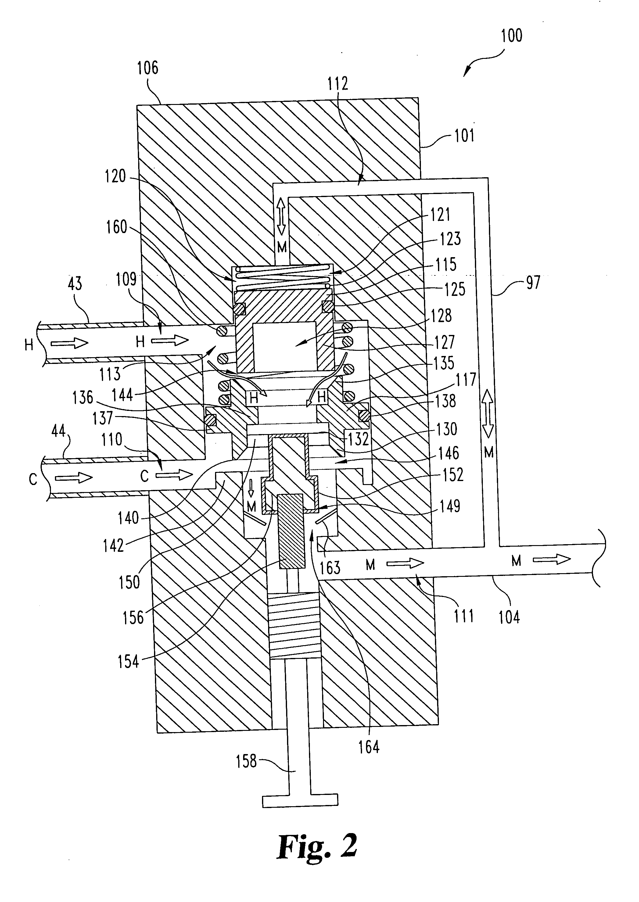
[0015]FIG. 1 illustrates a flow control system 30 according to one embodiment of the present invention. As illustrated, system 30 includes a flow control valve 32 that regulate...


PUM


Abstract

A fluid control system includes a valve and a restrictor. The valve is configured to regulate the proportion at which a first fluid and a second fluid are mixed together. Based on the pressure drop across the restrictor, the valve further regulates the overall flow rate of the mixed first and second fluids. In one form, the valve includes a pair of spools that regulate the proportion and flow rate of the fluids. In another form, the valve includes a thermostatic element that regulate the proportion at which the first and second fluids are mixed together so as to control the temperature of the mixed fluids. The valve in a further form incorporates a pair of diaphragm valves.

Description

BACKGROUND [0001] The present invention generally concerns flow control valves, and more specifically, but not exclusively, concerns a flow control valve that is able to regulate fluid flow and temperature during both low and high flow conditions. [0002] Comfort and safety are always a concern when designing water control systems for showers or baths. One typical problem that arises during showering (or taking a bath) is the shower's inability to maintain a constant temperature due to variations in supply pressure or in coming water temperature. Many have experienced the unpleasant effects of momentarily being sprayed by frigid water in a shower due to the operation of a dishwasher or washing machine. Even worse, serious burns and other injuries can result when the supply of cold is reduced during the shower, such as when a toilet is flushed or a lawn sprinkler system is activated. It is therefore desirable to maintain a proper flow balance between the hot and cold water in the show...

Claims


Application Information

Patent Timeline
Patent Type & Authority Applications(United States)
IPC IPC(8): B05B1/08B05B7/32B05B12/08B05B12/14F16K7/00F16K11/10F16K31/64G05D23/13
CPCB05B7/32B05B12/085G05D23/1393B05B12/1436G05D23/1346B05B12/087Y10T137/86879
Inventor JONTE, PATRICK
Owner MASCO CORP
Learn More