Power management in an electromagnetic transponder

a power management and electromagnetic transponder technology, applied in the field of electromagnetical transponders equipped with batteries, can solve the problems of signal interpretation errors, no longer respected modulation index,

Active Publication Date: 2016-06-14
STMICROELECTRONICS INT NV
View PDF18 Cites 5 Cited by
  • Summary
  • Abstract
  • Description
  • Claims
  • Application Information

AI Technical Summary

Benefits of technology

[0009]Thus, an embodiment of the present invention aims at overcoming all or part of the disadvantages of usual electromagnetic transponders equipped with a battery.
[0010]An embodiment of the present invention aims at preserving the modulation index of the terminal, whether the transponder operates in battery mode or in remote-supply mode.
[0011]An embodiment of the present invention aims at simplifying the switching from one mode to the other.
[0012]An embodiment of the present invention aims at providing a solution which can be easily integrated in low-voltage technology.

Problems solved by technology

Problems may arise when the charge of the transponder battery is at a level such that the transponder attempts to draw power from the electromagnetic field during high levels of the transmission and to draw power from the battery during low levels.
In such a case, the modulation index is no longer respected, which may cause signal interpretation errors.

Method used


Image

  • Power management in an electromagnetic transponder
  • Power management in an electromagnetic transponder
  • Power management in an electromagnetic transponder

Examples


Embodiment Construction

[0029]The same elements have been designated with the same reference numerals in the different drawings. For clarity, only those elements which are useful to the understanding of the embodiments which will be described have been shown and will be detailed. In particular, the generation of the signals to be transmitted by a terminal has not been detailed, the described embodiments being compatible with usual transmissions. Further, circuits for using the signals received by the transponder have not been detailed either, the described embodiments being here again compatible with the current use of such transmissions.

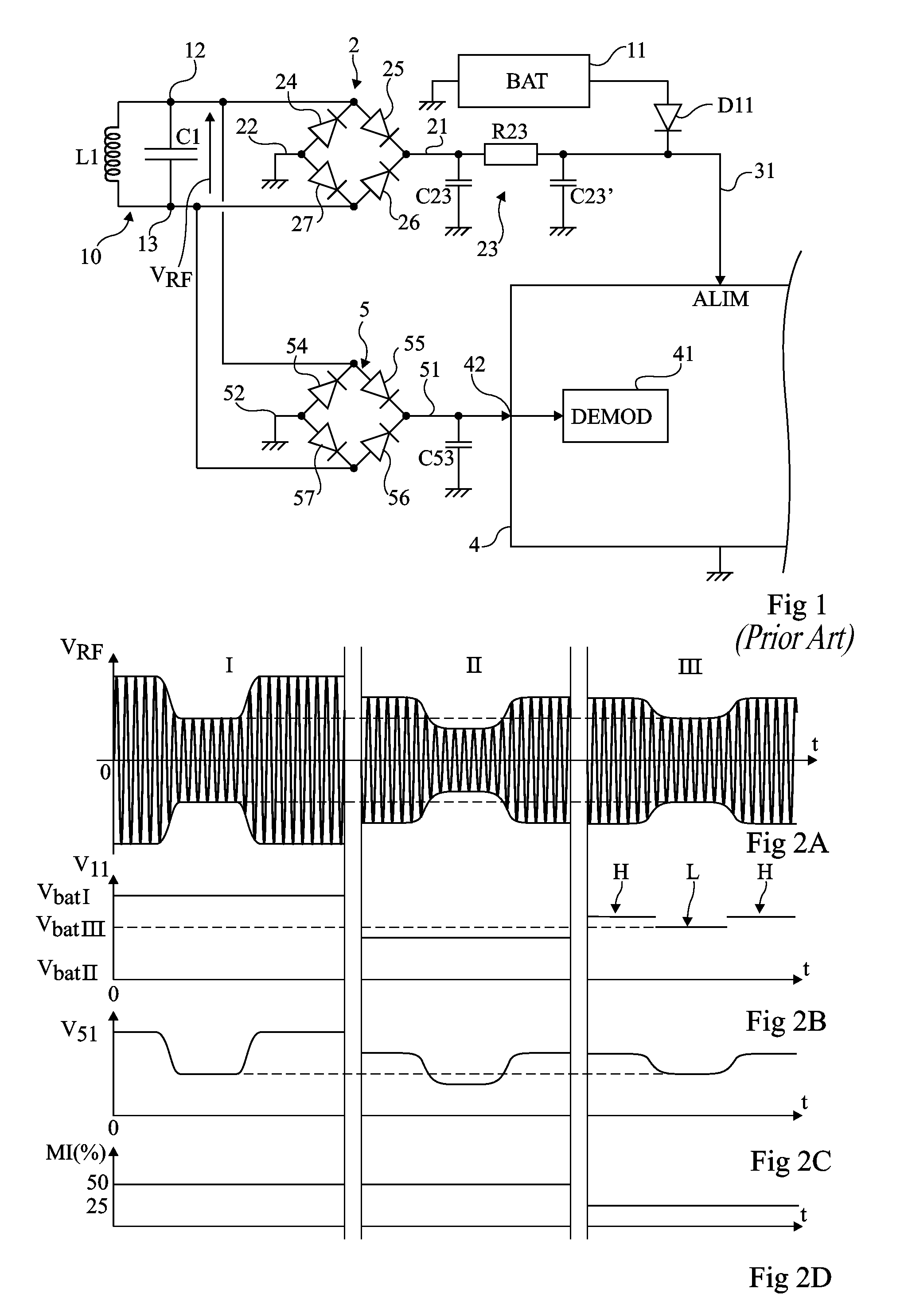
[0030]FIG. 1 very schematically shows an example of circuit forming a usual electromagnetic transponder.

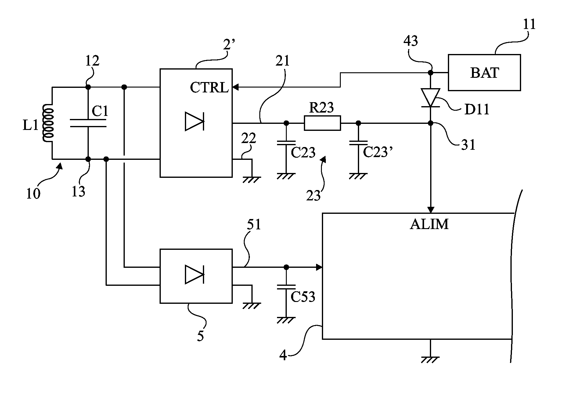
[0031]Such a transponder is based on the use of an oscillating circuit 10, for example, parallel, formed of an inductive element forming an antenna and of a capacitive element C1 in parallel. This oscillating circuit is intended to detect a high-frequency electromagnetic...


PUM


Abstract

An electromagnetic transponder includes an oscillatory circuit, a battery and a first rectifier bridge. Alternating current input terminals of the rectifier bridge are connected to the terminals of the oscillatory circuit, and at least two rectifier elements of the rectifier bridge are controllable on the basis of the voltage supplied by the battery.

Description

BACKGROUND[0001]1. Technical Field[0002]The present disclosure generally relates to electronic circuits and, more specifically, to electromagnetic transponders equipped with a battery.[0003]A field of application of the present invention relates to so-called NFC (Near Field Communication) devices, which are most often mobile telecommunication devices equipped with near-field communication circuits.[0004]2. Description of the Related Art[0005]Most devices provided with a battery and with a near-field communication router are designed to be powered by the battery when available or to be remotely supplied by extracting power from an electromagnetic field radiated by a terminal in the absence of a battery or when said battery is not available or discharged.[0006]A transmission from a terminal to a transponder is generally performed in amplitude modulation of a high-frequency carrier (for example, at 13.56 MHz). Since the carrier must be able to supply power to the transponder when it is...

Claims


Application Information

Patent Timeline
Patent Type & Authority Patents(United States)
IPC IPC(8): G06K19/07G06K19/077
CPCG06K19/0701G06K19/0702G06K19/0705G06K19/0709G06K19/07749
Inventor TRAMONI, ALEXANDRE
Owner STMICROELECTRONICS INT NV
Why Eureka
Try Eureka