Condensate discharge device for compressed gas systems

a technology of compressed gas and condensate, which is applied in the direction of valve arrangement, mechanical equipment, instruments, etc., can solve the problems of high energy loss caused by compressed air discharge, low production efficiency of condensate discharge devices of this type, and inability to operate normally, etc., to achieve the effect of auxiliary functions, reduced structure and high production efficiency

Inactive Publication Date: 2016-06-28
BEKO TECHNOLOGIES GMBH
View PDF29 Cites 5 Cited by
  • Summary
  • Abstract
  • Description
  • Claims
  • Application Information

AI Technical Summary

Benefits of technology

[0013]In the sense of the present invention, the term “tubular body” should be broadly interpreted and generally describes an elongated hollow body, the length whereof is much greater than its diameter. The cross-sectional shape of the tubular body is not particularly prescribed or limited by the term “tubular body”. Even though a circular cross-section is regarded as an optimum design for the most frequent cases of application, the cross-section can also have rectangular, oval or other shapes, for example to increase the rigidity.
[0024]According to a further advantageous embodiment of the invention, the valve assembly comprises a control valve, in particular a solenoid valve, and a discharge valve, in particular a diaphragm valve, wherein it is possible with the control valve to build up or reduce an auxiliary pressure between the control valve and the discharge valve and the pressure medium for the auxiliary pressure can be withdrawn from the hollow space. In this way, the auxiliary pressure can be generated particularly efficiently for the control of the discharge valve, since the pressure medium in the hollow space is already under pressure due to the pressure of the compressed gas system. Furthermore, a constantly condensate-free pressure medium is available by means of the hollow space, so that the control valve is not contaminated or damaged by condensate deposits or solid components entrained in the condensate.

Problems solved by technology

The condensate discharge devices constituted as float-type discharge devices find very widespread use on account of their ability to be produced at low cost, but they are also susceptible to malfunction.
A drawback is opening in the absence of condensate, as a result of which high energy losses are caused by discharged compressed air.
Condensate discharge devices of this type are relatively expensive in production, but on the other hand are characterized by a very cost-effective operation, for which reason considerable cost advantages can be achieved with the electronically level-regulated condensate discharge devices over their entire operating life.
The installation space for the condensate discharge device is often limited, for example by the ground clearance or the visibility of the control panel of the condensate discharge device.
Since, however, the aforementioned condensate discharge devices can be mounted only in a specific mounting position, for example either only horizontal or only vertical, due for example to the establishment of the clean inner protection zone or the installation position of the sensor, recourse is taken to additional adapters or extensions or aids in cases in which a direct connection to the compressed gas system is not possible on account of the installation space.

Method used


Image

  • Condensate discharge device for compressed gas systems
  • Condensate discharge device for compressed gas systems
  • Condensate discharge device for compressed gas systems

Examples


Embodiment Construction

[0031]In the various figures, identical parts are always provided with the same reference numbers, so that as a rule they are described only once.

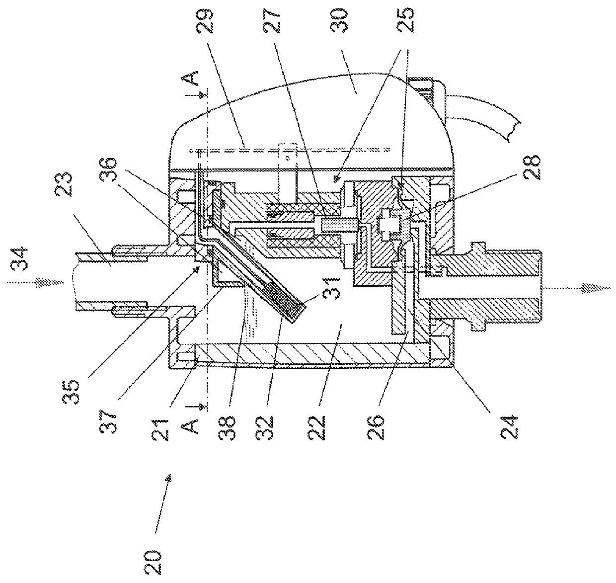
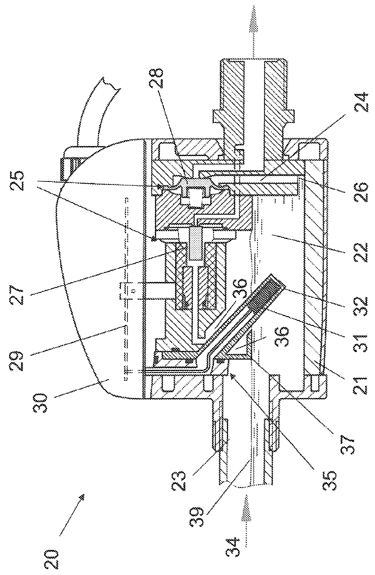
[0032]FIG. 1 shows a cross-sectional side view of an example of embodiment of a condensate discharge device 20 according to the invention for compressed gas systems, in particular for compressed air systems, in a first, vertical mounting position. Condensate discharge device 20 comprises a housing 21, which comprises a condensate collecting chamber 22. Condensate collecting chamber 22 can be connected via a condensate feed 23 to the compressed gas system not represented in detail in FIG. 1. Condensate from the compressed gas system can flow via condensate feed 23 to condensate collecting chamber 22. The condensate passes out of condensate collecting chamber 22 again via a condensate drain 24. Condensate drain 24 can be closed by means of a valve assembly 25. As can be seen in FIG. 1, a mouth 26 of condensate drain 24 is disposed in a left-...


PUM


Abstract

The invention relates to a condensate discharge device for compressed gas systems, comprising a housing (21), which has a condensate collecting chamber (22) that can be connected to the compressed gas system by means of a condensate feed (23) and which has a condensate drain (24) that can be closed by means of valve assembly (25), and comprising a tubular body (32) protruding into the condensate collecting chamber (22) for accommodating at least one electronic filling level measuring device (31), by means of which the condensate filling level in the condensate collecting chamber (22) can be detected, wherein the housing (21) can be mounted in a first, vertical mounting position and a second, horizontal mounting position and the longitudinal axis of the tubular body (32) extends at an angle to the condensate feed direction (34).

Description

TECHNICAL FIELD[0001]The invention relates to a condensate discharge device for compressed gas systems, in particular compressed air systems.BACKGROUND[0002]Such condensate discharge devices are used for example in compressed air technology in order to remove the condensate usually arising in the pressure line network from the latter, which condensate can also contain oil or rust, apart from water. The condensates arise from the moisture in the surrounding air, which is sucked in by the compressed air compressor. The oil essentially originates from the compressors in which it is used as a lubricant, whereas the rust usually originates from the compressed air lines.[0003]Various designs of condensate discharge devices are known. They usually work in such a way that a valve is opened, as a result of which the condensate is expelled from the compressed air network by the pressure. In this process, the gas or compressed air loss has to be kept as low as possible for reasons of efficienc...

Claims


Application Information

Patent Timeline
Patent Type & Authority Patents(United States)
IPC IPC(8): F16T1/00F16T1/38F16K51/00F16T1/14G05D9/12
CPCF16K51/00F16T1/00F16T1/14F16T1/38G05D9/12Y10T137/3052Y10T137/3077Y10T137/3105Y10T137/5907Y10T137/7306
Inventor SCHLENSKER, HERBERTSINSTEDTEN, JOHANNES
Owner BEKO TECHNOLOGIES GMBH
Why Eureka
Try Eureka