Device for actuating a locking mechanism

a technology for locking mechanisms and devices, applied in the direction of gearing control, belts/chains/gearrings, gearing elements, etc., can solve the problems of not being able to disengage the parking lock without the release device, parking lock cannot be no longer engaged, parking lock

Active Publication Date: 2016-07-05
ZF FRIEDRICHSHAFEN AG
View PDF16 Cites 6 Cited by
  • Summary
  • Abstract
  • Description
  • Claims
  • Application Information

AI Technical Summary

Benefits of technology

[0011]Accordingly, the purpose of the present invention is to provide a device for actuating a locking mechanism, by means of which safety-critical operating conditions can be avoided if a fault occurs.
[0017]By means of both devices according to the invention an erroneous release of the locking mechanism or a change of the locking mechanism to an open operating condition when the electromagnet is energized due to erroneous action upon the piston unit with an actuating pressure that acts in the direction of an axial position equivalent to the open condition of the locking mechanism is avoided in a simple manner, so that safety-critical operating conditions of a vehicle incorporating the device do not occur in the event of a fault.
[0022]In an advantageous further development of the device according to the invention, the release element and the armature element are functionally connected to one another in a simply designed manner by way of an armature rod.
[0024]In an embodiment of the device according to the invention that can also be produced simply and inexpensively, the at least one blocking element for activating the retaining element can be guided by the release element into recesses of the piston unit or an area functionally connected thereto.
[0026]If surfaces of the release element and of the first recess that co-operate with the blocking element are matched with one another in such manner that when the electromagnet is in its energized operating condition the blocking element can be held by the release element in the first recess, whereas when the electromagnet is not energized the blocking element can be moved by the spring force acting on the piston unit out of the first recess, then in a simple manner this ensures that the retaining device acted upon by the spring force on the piston unit can be kept in its activated operating condition by a small electromagnetic holding force, whereas when the electromagnet is not energized the retaining device changes to its deactivated operating condition in order to change the locking mechanism to the open operating condition and to be able to engage a parking lock device.
[0027]If surfaces of the release element and of the second recess that co-operate with the blocking element are matched to one another in such manner that when the electromagnet is energized the blocking element can be held by the release element in the second recess, whereas when the electromagnet is not energized the blocking element can be moved by a hydraulic force acting on the piston unit out of the second recess, this ensures that the release element can be actuated by means of the electromagnet without any action by an external force and in the event that the piston unit is erroneously acted upon by the hydraulic pressure, the axial force that results from this hydraulic pressure and acts upon the piston unit does not deactivate the retaining device, so that undesired opening of the locking mechanism and release of the parking lock device are avoided.

Problems solved by technology

Thus, it is not possible to disengage the parking lock without the release device if the working pressure is no longer high enough.
Disadvantageously, below the necessary pressure level, after being released by the spring the parking lock can no longer be engaged, since a corresponding pressure level is required for that.
This means that the parking lock, which has been changed to its open operating condition by the spring, can only be engaged again by acting upon it appropriately with hydraulic pressure.
If a corresponding functional defect occurs in the area of the hydraulic system or in the area of the electrical system that supplies current to the mechanical locking magnet, the parking lock is released or even not engaged to begin with, which in some circumstances, however, can give rise to safety-critical operating conditions of a vehicle made with the parking lock system.

Method used


Image

  • Device for actuating a locking mechanism

Examples


Embodiment Construction

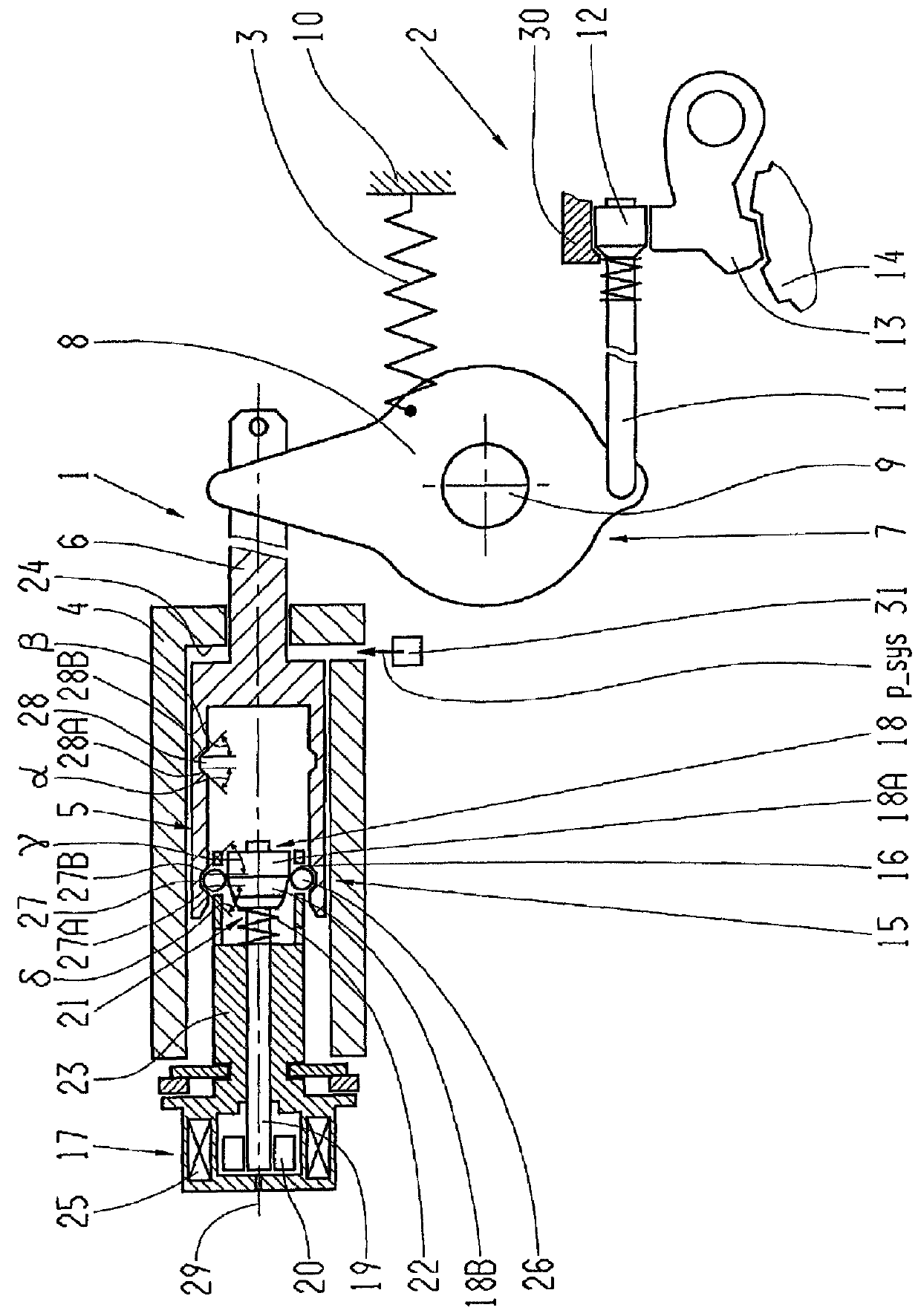
[0031]The FIGURE shows a schematic partial longitudinal section of a device 1 for actuating a locking mechanism 2 in this case designed as a parking lock device. In a manner known per se, the device 1 comprises a piston unit 5 arranged to move in the axial direction in a cylinder 4, which piston can be acted upon by a fluid and depending on the fluid pressure can be actuated in the opening direction of the locking mechanism 2 in opposition to a spring device 3 that acts in the closing direction of the locking mechanism 2, which is connected by a drive-pin 6 to a guide mechanism 7. In this case the guide mechanism 7 comprises a rotary plate 8 which is mounted to rotate in the area of a bolt 9. In this case the spring device 3 is in the form of a tension spring connected at one end to the rotary plate 8 and supported at the other end in the area of a housing 10. In addition the rotary plate 8 is functionally connected to a parking lock rod 11 which is coupled to a parking lock cone 12...


PUM


Abstract

A device for actuating a locking mechanism, in particular for actuating a parking lock of a vehicle having an automatic transmission. The device comprises a piston which axially moves, a retaining device which is self-activating when the piston is in an axial position in which the locking mechanism is open to hold the piston in the axial position in which the locking mechanism is open, and an actuating device for actuating a release element, which deactivates the retaining device. To hold the piston in an axial position in which the locking mechanism is closed, the retaining device is self-activating, and can be deactivated to enable the piston to move, starting from the axial position in which the locking mechanism is closed, to the axial position in which the locking mechanism is open.

Description

[0001]This application is a National Stage completion for PCT / EP2013 / 059125 filed May 2, 2013, which claims priority from German patent application serial no. 10 2012 210 571.9 filed Jun. 22, 2012.FIELD OF THE INVENTION[0002]The invention concerns a device for actuating a locking mechanism.BACKGROUND OF THE INVENTION[0003]A parking lock actuating device and a driving gear selector device for an automatic transmission of a motor vehicle are known from DE 102 45 386 A1. The parking lock actuating device is made with a parking lock cone by means of which the parking lock can be engaged and disengaged. In one of the embodiments of the parking lock actuating device shown, one end of the parking lock cone is connected to a lever mounted to swivel on a bearing. When the lever is swiveled about the bearing the parking lock is displaced in the axial direction. The lever is connected by a rod to an actuating piston or piston unit, which is arranged to move axially in a cylinder. Between the a...

Claims


Application Information

Patent Timeline
Patent Type & Authority Patents(United States)
IPC IPC(8): F16H63/34F16H63/38
CPCF16H63/3458F16H63/34F16H63/3416F16H63/3483F16H63/3475
Inventor POPP, CHRISTIANMESCHENMOSER, STEFANSCHMIDT, THILO
Owner ZF FRIEDRICHSHAFEN AG
Why Eureka
Try Eureka