Shifting device for a manual transmission

a shifting device and manual transmission technology, applied in mechanical equipment, wound springs, transportation and packaging, etc., can solve the problems of asymmetric distribution and transfer of shifting force, large structural space occupied by the gears, and large shifting force needed to engage and disengage the gears, so as to reduce the rigidity of the rocker arm spring, the effect of simple and inexpensive production

Inactive Publication Date: 2010-04-29
ZF FRIEDRICHSHAFEN AG
View PDF9 Cites 2 Cited by
  • Summary
  • Abstract
  • Description
  • Claims
  • Application Information

AI Technical Summary

Benefits of technology

[0018]To produce the extension of the force transfer path that is important for reducing the spring rigidity of the rocker arm, it is expediently provided that the outer spiral curve of the spiral spring extends from the bearing point as far as under the slide-block holder, and the inner spiral curve of the spiral spring extends from there to the slide-block holder.
[0019]The shift rocker according to the invention, with its rocker bridge, the two rocker arms and the carrier element, can be produced simply and inexpensively as an integrated aluminum pressure-diecast component. It is also possible, however, to produce the shift rocker according to the invention as a pressed and stamped sheet component, in which the plurality of individual parts are welded together where necessary or connected permanently to one another in some other way.

Problems solved by technology

The disadvantages of a shifting device of this type, however, are the relatively large structural space they occupy for the arrangement and mounting of the shift rods, and the comparatively large shifting forces needed to engage and disengage the gears.
However, this has the disadvantage that the shifting force is applied asymmetrically to the shift rocker and the shifting force is transferred unequally, via the rocker arms of the shift rockers, to the respective shift sleeve.
Besides this unfavorable force transfer, the intensive contact of the shift sleeve with the more rigid, shorter part of the shift rocker also favors an undesired transmission of oscillations and vibrations from the transmission to the manual shift lever or gear control element of the shifting device.
However, owing to the effective lever arm between the carrier element and the rail weld, there is a tilting torque which results in asymmetrical distribution and transfer of a shifting force in or via the two rocker arms.
However, the asymmetrical distribution and transfer of a shifting force from the carrier element in or via the two rocker arms is still a disadvantage.
But since the elasticity of both rocker arms is determined essentially by the considerably smaller material thickness of the outer leg, the efficacy of this known design is questionable.
Besides, reducing the cross-section of one of the rocker arms can reduce the fatigue strength of the shift rocker.

Method used


Image

  • Shifting device for a manual transmission
  • Shifting device for a manual transmission
  • Shifting device for a manual transmission

Examples


Embodiment Construction

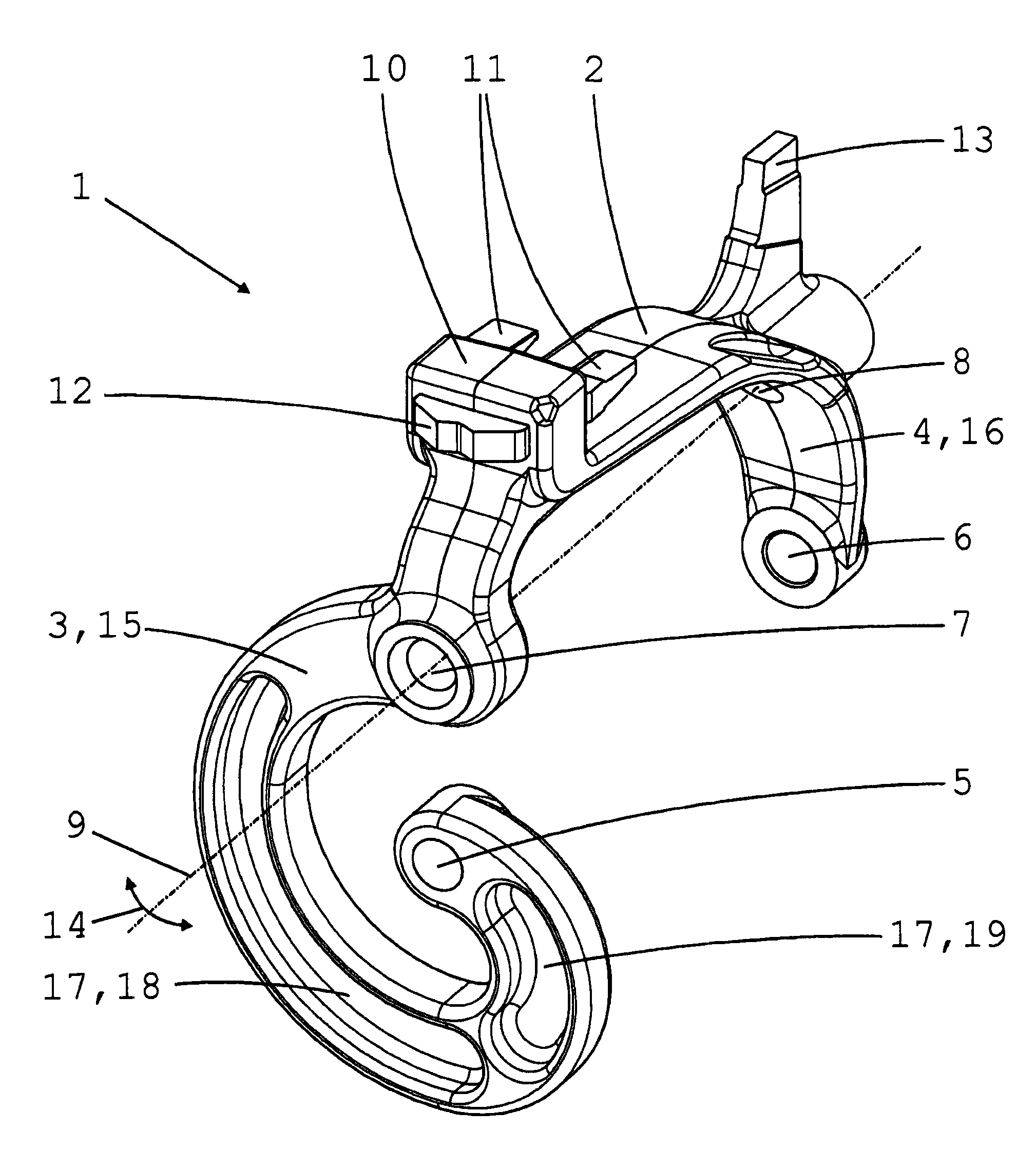
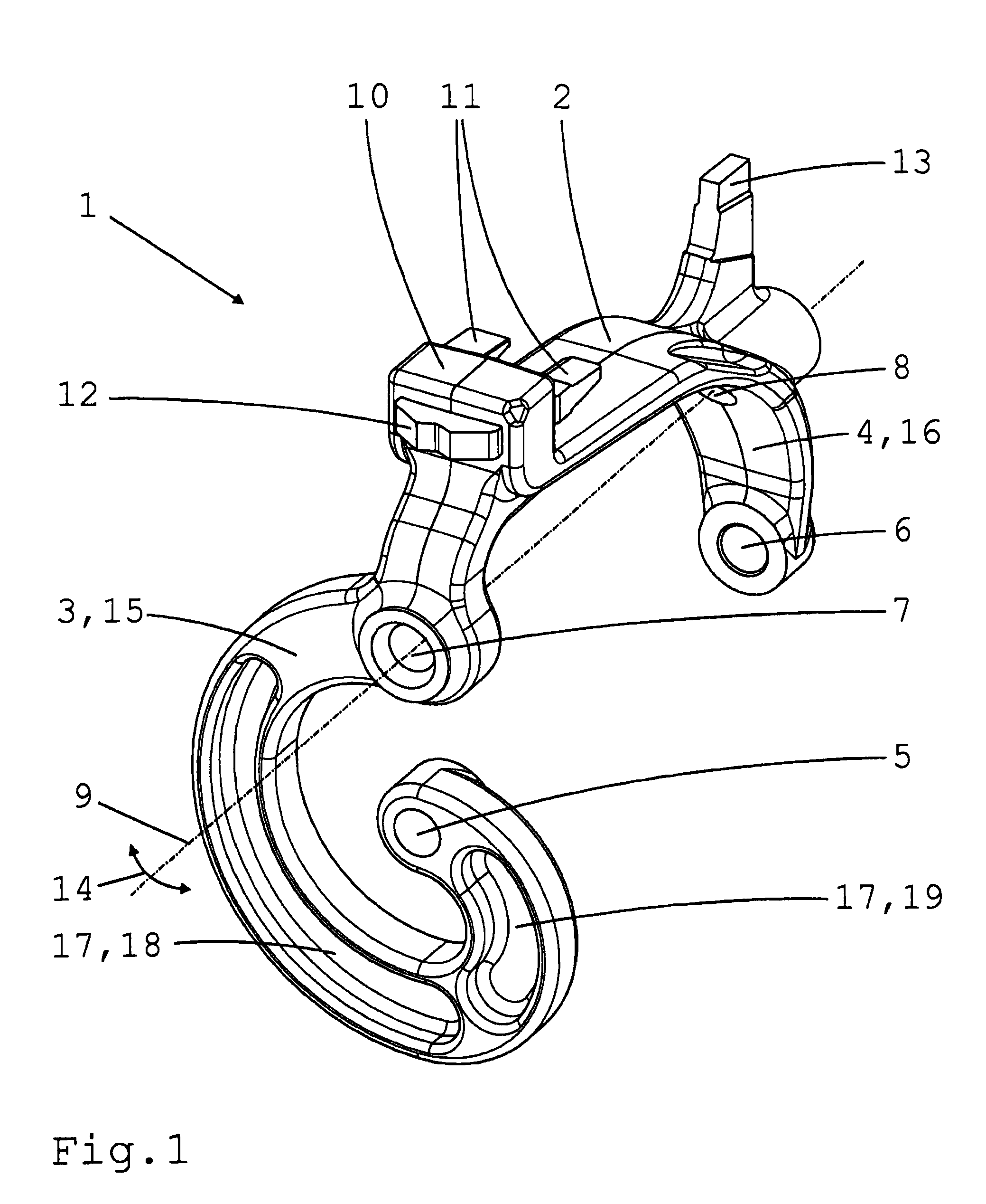
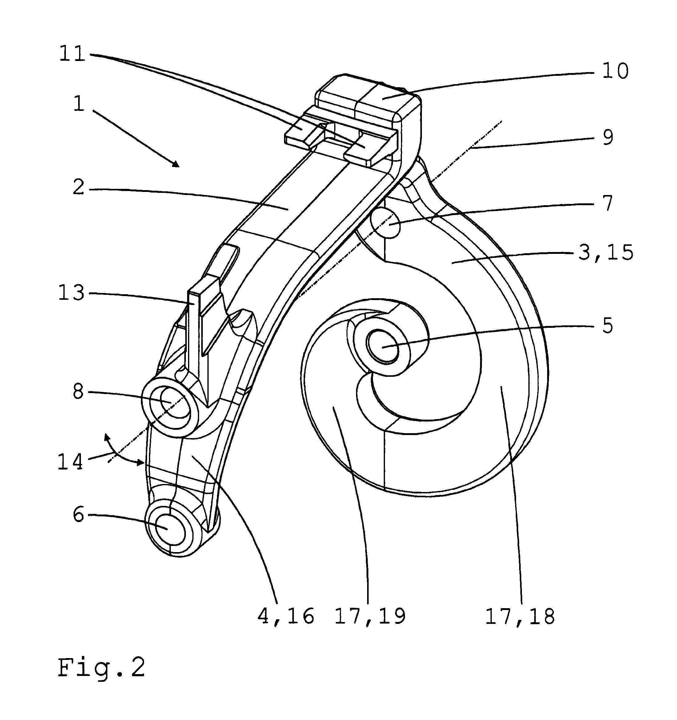
[0023]The shift rocker 1 illustrated in different perspective views in FIGS. 1 and 2 has a basic U-shape and consists of two rocker arms 3, 4 connected to one another by a rocker bridge 2. Each rocker arm 3, 4 is provided at its end with a holding bore 5, 6 for the attachment of a respective slide-block (not shown), the latter being provided in order to engage in an outer annular groove of an associated shift sleeve. Two bearing bores 7 and 8 arranged respectively in each rocker arm 3, 4, into which bearing bolts which can be fixed to the housing can be inserted, determine a transverse axis 9 about which the shift rocker 1 is mounted to pivot when in the assembled condition. On the rocker bridge 2 in an off-center position is arranged a supporting block 10 which supports an inward-directed, fork-shaped carrier element 11 for engaging a shifting pin of a transmission shaft, and an outward-directed detent element 12 with a detent recess for engaging a detent element fixed on the housi...


PUM


Abstract

A shifting device for a manual transmission having a shift rocker formed by two rocker arms connected by a rocker bridge, which is arranged over a shift sleeve via two slide-blocks attached to a holder at the end of each rocker arm, which pivots about a transverse axis defined by bearing points. A carrier element is positioned off-center on the rocker bridge to engage with a shifting pin of a shifting shaft. The rocker arm closer to the carrier element has a lower elastic rigidity than the other rocker arm. To produce different spring rigidities, the rocker arm closer to the carrier element has the geometrical form of a spring element which is elastic in the pivoting direction. The, rocker arm farther away from the carrier element is a bracket with relatively greater elastic rigidity.

Description

[0001]This application claims priority from German patent application serial no. 10 2008 043 274.1 filed Oct. 29, 2008.FIELD OF THE INVENTION[0002]The invention concerns a shifting device for a manual transmission, with at least one shift rocker which has a basic U-shape formed by two rocker arms connected to one another by a rocker bridge, which is arranged over a shifting packet of a transmission shaft comprising a shift sleeve, which is engaged with an annular groove of the shift sleeve by virtue of two slide-blocks respectively attached at the ends to a holder on each rocker arm, which is mounted to pivot about a transverse axis determined by two bearing points respectively arranged one on each rocker arm, and which comprises a carrier element arranged off-center on the rocker bridge in order to engage with a shifting pin of a shifting shaft arranged axis-parallel in relation to the transmission shaft, and such that the rocker arm closer to the carrier element has a lower elasti...

Claims


Application Information

Patent Timeline
Patent Type & Authority Applications(United States)
IPC IPC(8): F16H63/30F16H59/04
CPCF16H63/32Y10T74/19251Y10T74/20177F16H2063/325
Inventor BEER, UWE
Owner ZF FRIEDRICHSHAFEN AG
Why Eureka
Try Eureka