Extension for a shock absorber

a technology of extension shaft and shock absorber, which is applied in the manufacture of shock absorbers, liquid based dampers, springs/dampers, etc., can solve the problems of inability to indicate the connection of tubular extension shaft and base, tight axial installation space in the chassis, and inability to manufacture simple and inexpensively

Active Publication Date: 2018-10-16
ZF FRIEDRICHSHAFEN AG
View PDF15 Cites 2 Cited by
  • Summary
  • Abstract
  • Description
  • Claims
  • Application Information

AI Technical Summary

Benefits of technology

[0005]It is an object of the present invention to realize an extension that can be produced simply and inexpensively.
[0007]The bend pleat provides an axial distance of the base with respect to an end-side end face of the extension shaft and provides for an appreciable strengthening of the entire structural component part. Compared with a weld construction between the tubular body and the base, a tightness inspection can be dispensed with.
[0011]To minimize the total weight of the cylinder, the tube portion has a greater wall thickness than the cylinder. Both structural component parts can be exactly configured to their loads and can be constructed optimally through separate fabrication.
[0013]The base is preferably shaped convexly in direction of the tube portion. This constructional shape stiffens the base and offers a reliable self-centering supporting surface, e.g., for a base valve arranged in the cylinder.
[0018]One advantage is that a dimensionally stable connection, which is tight against pressurized medium, is achieved between the base and the tubular body. In addition, a tubular body is very rigid in proportion to its own weight. Chip-removing post-machining is not necessary, i.e., the structural component part is finished when it leaves the shaping device.

Problems solved by technology

In many vehicles, there is the problem that the available axial installation space in the chassis is very tight.
However, the opposite situation also exists, particularly in larger vehicles.
However, there is no indication of how the tubular extension shaft is connected to the base.

Method used


Image

  • Extension for a shock absorber
  • Extension for a shock absorber
  • Extension for a shock absorber

Examples


Embodiment Construction

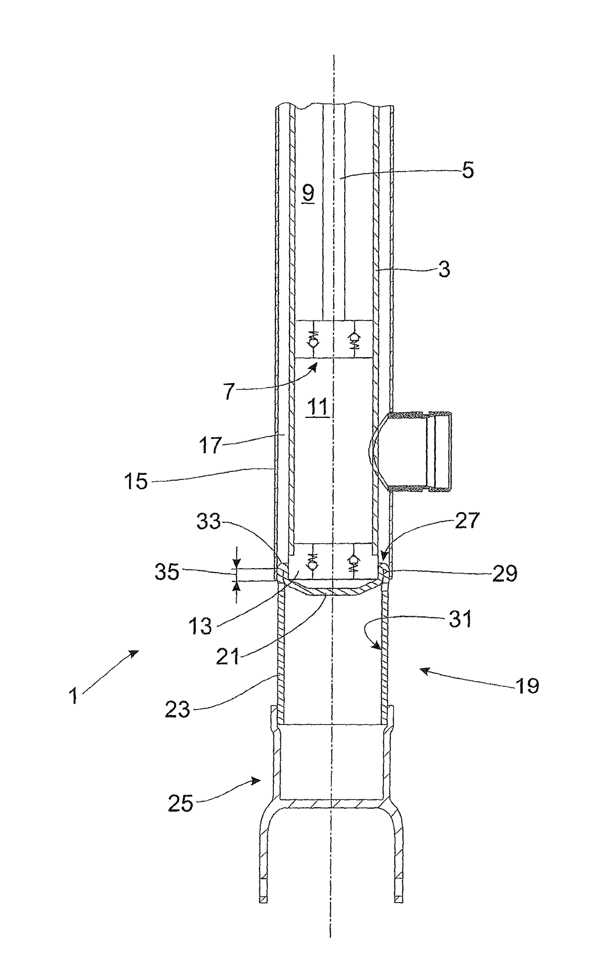
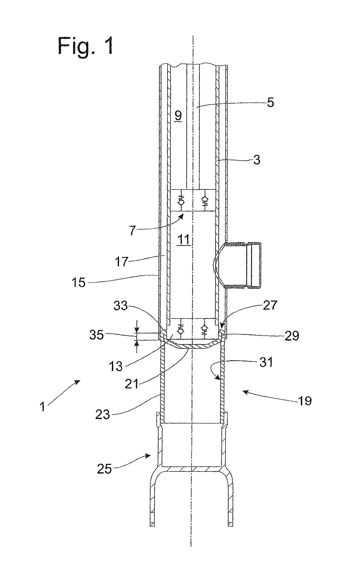
[0023]FIG. 1 shows a vibration damper 1 with an inner cylinder 3 in which a piston rod 5 together with a piston 7 outfitted with a valve executes an axial displacing movement. The piston 7 divides the cylinder 3 into a working chamber 9 proximal to the piston rod and a working chamber 11 distal to the piston rod, both of which working chambers 9; 11 are completely filled with damping medium.

[0024]The inner cylinder 3 is bounded at the end side by a base valve body 13 on which the inner cylinder 3 is axially supported and radially centered. An outer cylinder 15 envelopes the inner cylinder 3. An annular space between the inner cylinder 3 and outer cylinder 15 forms a compensation space 17 for the damping medium volume displaced by the piston rod 5, this compensation space 17 being only partially filled with damping medium.

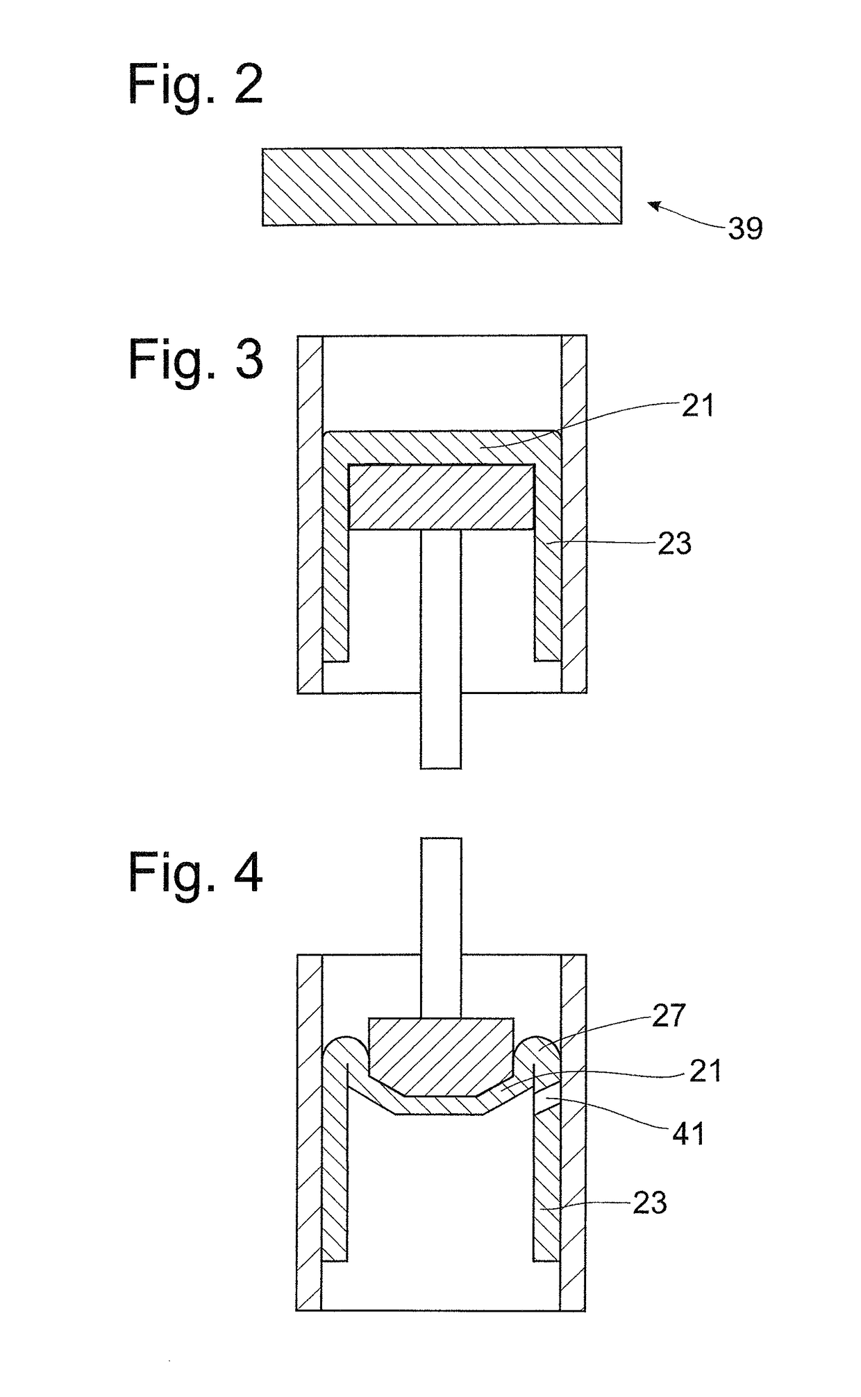
[0025]Following the outer cylinder 15 in axial direction is a extension 19 that has a base 21 for the outer cylinder 15 and a tube portion 23 to a connection member...


PUM


Abstract

Extension for a cylinder of a vibration damper comprising a base and a tube portion adjoining the latter. The base and the tube portion are formed in one piece. The tube portion has a circumferential bend pleat with respect to the base.

Description

BACKGROUND OF THE INVENTION[0001]1. Field of the Invention[0002]The invention is directed to an extension for a vibration damper (shock absorber) and a method for producing it.[0003]2. Description of the Related Art[0004]In many vehicles, there is the problem that the available axial installation space in the chassis is very tight. However, the opposite situation also exists, particularly in larger vehicles. DE 10 2006 016 701 A1 describes solutions for minimizing particularly the damping medium requirement or piston rod length. Disclosed is a cylinder which is optimized with respect to the maximum compression path is used in combination with an extension shaft. A connection member is fastened to this extension shaft. In DE 10 2006 016 701 A1, the extension shaft and a base of the cylinder are constructed in one part as a forging, and the extension shaft is formed by pipe. However, there is no indication of how the tubular extension shaft is connected to the base.SUMMARY OF THE INVE...

Claims


Application Information

Patent Timeline
Patent Type & Authority Patents(United States)
IPC IPC(8): F16F9/32F16F9/18
CPCF16F9/3235F16F2226/00F16F9/3257F16F9/185F16F9/54F16F9/3242F16F2226/04
Inventor DREHER, ROBERTRAMER, SEBASTIANKEMMER, RALFZIELECKI, KRZYSZTOF
Owner ZF FRIEDRICHSHAFEN AG
Why Eureka
Try Eureka