Tunable wireless power architectures

a wireless power architecture and wireless technology, applied in the direction of charging stations, cores/yokes, transportation and packaging, etc., can solve the problems of reducing the efficiency of energy transfer, affecting the efficiency of wireless energy transfer, and limiting the prior art wireless energy transfer systems

Active Publication Date: 2016-07-05
WITRICITY CORP
View PDF806 Cites 31 Cited by
  • Summary
  • Abstract
  • Description
  • Claims
  • Application Information

AI Technical Summary

Problems solved by technology

Prior art wireless energy transfer systems have been limited by a variety of factors including concerns over user safety, low energy transfer efficiencies and restrictive physical proximity / alignment tolerances for the energy supply and sink components.
One particular challenge in wireless energy transfer is control and tuning of the resonator structures and the power source to deliver controlled power to a load.
Coupling between the source and device may change reducing the efficiency of energy transfer for example.
Changes in the wireless energy transfer characteristics may change the power delivered to the load or cause unwanted fluctuations in the power delivered to a load at the device.

Method used


Image

  • Tunable wireless power architectures
  • Tunable wireless power architectures
  • Tunable wireless power architectures

Examples


example system embodiments

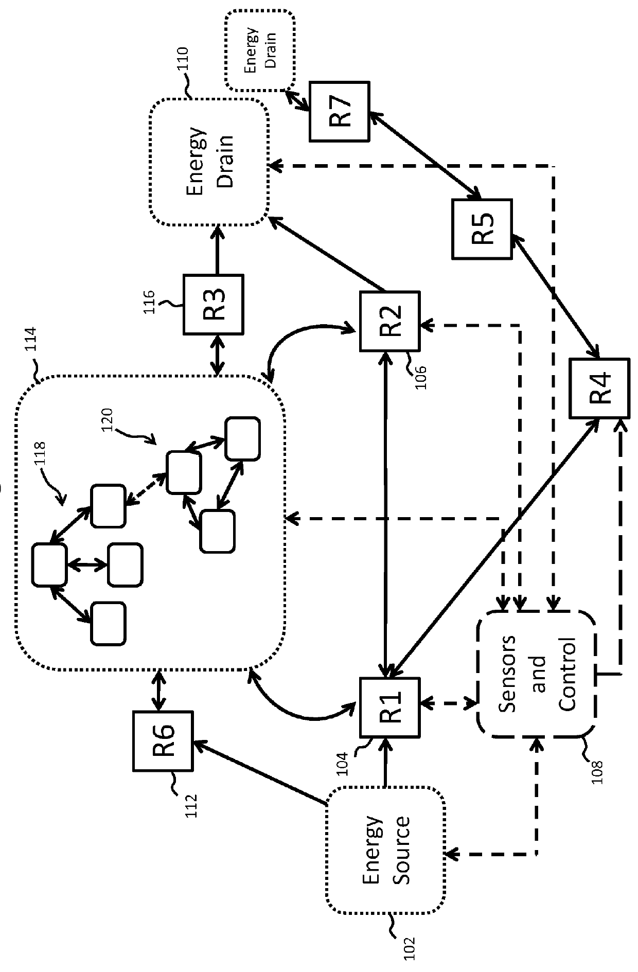
[0241]FIG. 24 shows an exemplary block diagram of a wireless energy transfer system in accordance with the present invention. The system in FIG. 24 includes a wireless energy source that transfers energy to at least one wireless energy capture device. The system comprises tunable source elements and tunable device elements capable of adjusting the energy transfer of the system. The adjustment of energy transfer may be used to control the amount of energy transferred to the device. The adjustment may be used to control the power delivered to the load under different loading conditions and different device positions / orientations relative to the source. The adjustment of energy transfer may be used to ensure that energy is transferred efficiently by reducing wasted or dissipated energy in the system elements due to excessive energy stored or flowing through the system elements.

[0242]The source of the system may comprise a tunable switching amplifier and a tunable impedance matching net...


PUM

PropertyMeasurementUnit
resonant frequenciesaaaaaaaaaa
poweraaaaaaaaaa

Abstract

Described herein are improved configurations for a wireless power transfer. The parameters of components of the wireless energy transfer system are adjusted to control the power delivered to the load at the device. The power output of the source amplifier is controlled to maintain a substantially 50% duty cycle at the rectifier of the device.

Description

CROSS-REFERENCE TO RELATED APPLICATIONS[0001]This application claims the benefit of U.S. provisional patent application 61 / 515,324 filed Aug. 4, 2011.BACKGROUND[0002]1. Field[0003]This disclosure relates to wireless energy transfer, methods, systems and apparati to accomplish such transfer, and applications.[0004]2. Description of the Related Art[0005]Energy or power may be transferred wirelessly using a variety of known radiative, or far-field, and non-radiative, or near-field, techniques as detailed, for example, in commonly owned U.S. patent application Ser. No. 12 / 613,686 published on May 6, 2010 as US 2010 / 010909445 and entitled “Wireless Energy Transfer Systems,” U.S. patent application Ser. No. 12 / 860,375 published on Dec. 9, 2010 as 2010 / 0308939 and entitled “Integrated Resonator-Shield Structures,” U.S. patent application Ser. No. 13 / 222,915 published on Mar. 15, 2012 as 2012 / 0062345 and entitled “Low Resistance Electrical Conductor,” U.S. patent application Ser. No. 13 / 283...

Claims


Application Information

Patent Timeline
Patent Type & Authority Patents(United States)
IPC IPC(8): H01F38/14H02J5/00H01F3/00
CPCH01F38/14H02J5/005H02J50/12H01F2003/005B60L2240/36H02J50/80B60L53/126Y02T90/14Y02T10/7072Y02T10/70H02J50/90H02J50/60H02J50/70Y02T90/12B60L53/12
Inventor KARALIS, ARISTEIDISKESLER, MORRIS P.HALL, KATHERINE L.PALLO, NATHAN ANDREW
Owner WITRICITY CORP
Why Eureka
Try Eureka