Eureka AIR delivers breakthrough ideas for toughest innovation challenges, trusted by R&D personnel around the world.

Adjusting brushhead for facial contours

a brushhead and contour technology, applied in the field of electric skin care appliances, can solve the problem of compromising the overall treatment of the facial area

Active Publication Date: 2016-07-12
LOREAL SA
View PDF5 Cites 7 Cited by
  • Summary
  • Abstract
  • Description
  • Claims
  • Application Information

AI Technical Summary

Problems solved by technology

This can be either difficult or inconvenient at times, so that the overall treatment of the facial area can be compromised.

Method used


Image

  • Adjusting brushhead for facial contours
  • Adjusting brushhead for facial contours
  • Adjusting brushhead for facial contours

Examples


Embodiment Construction

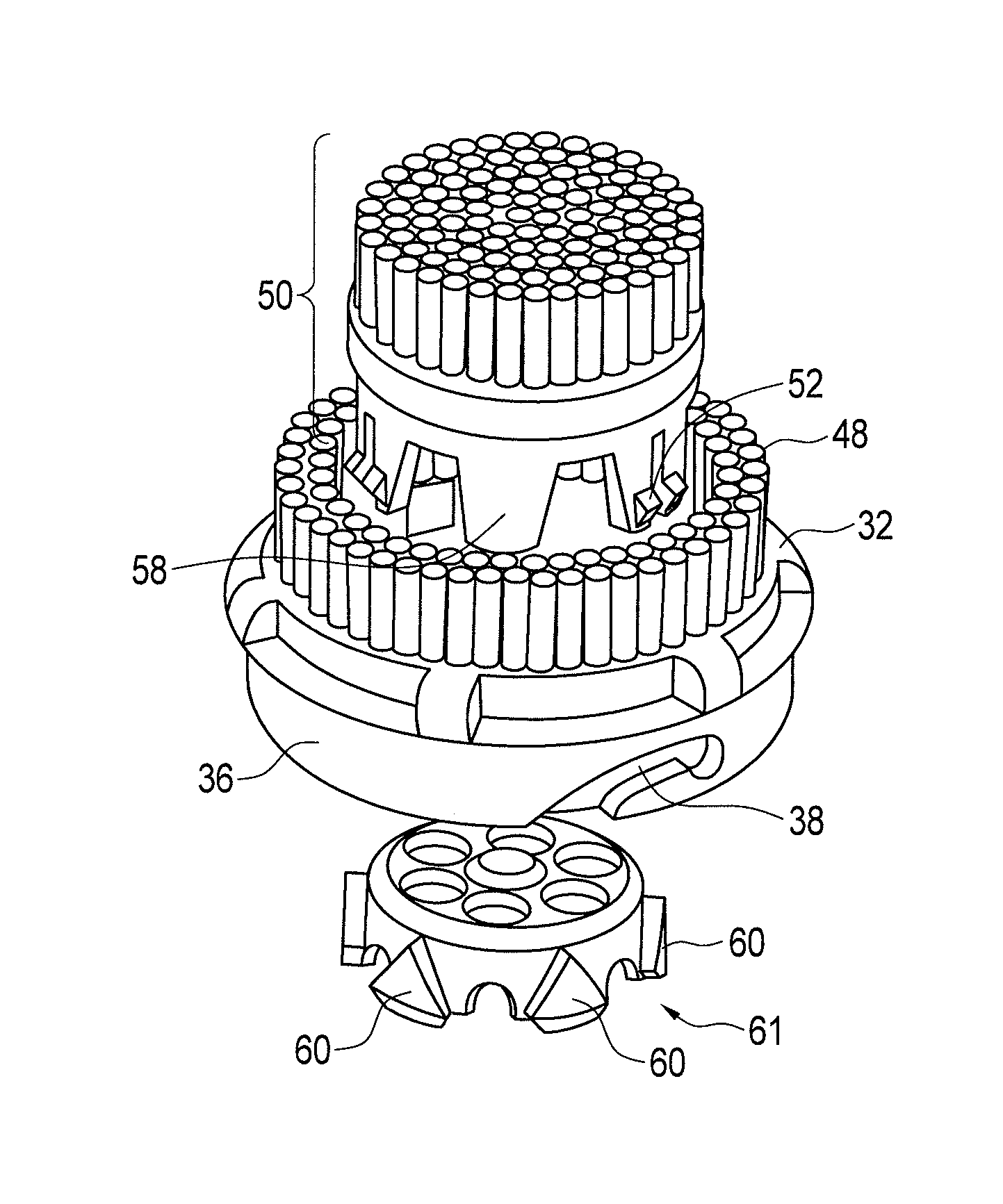
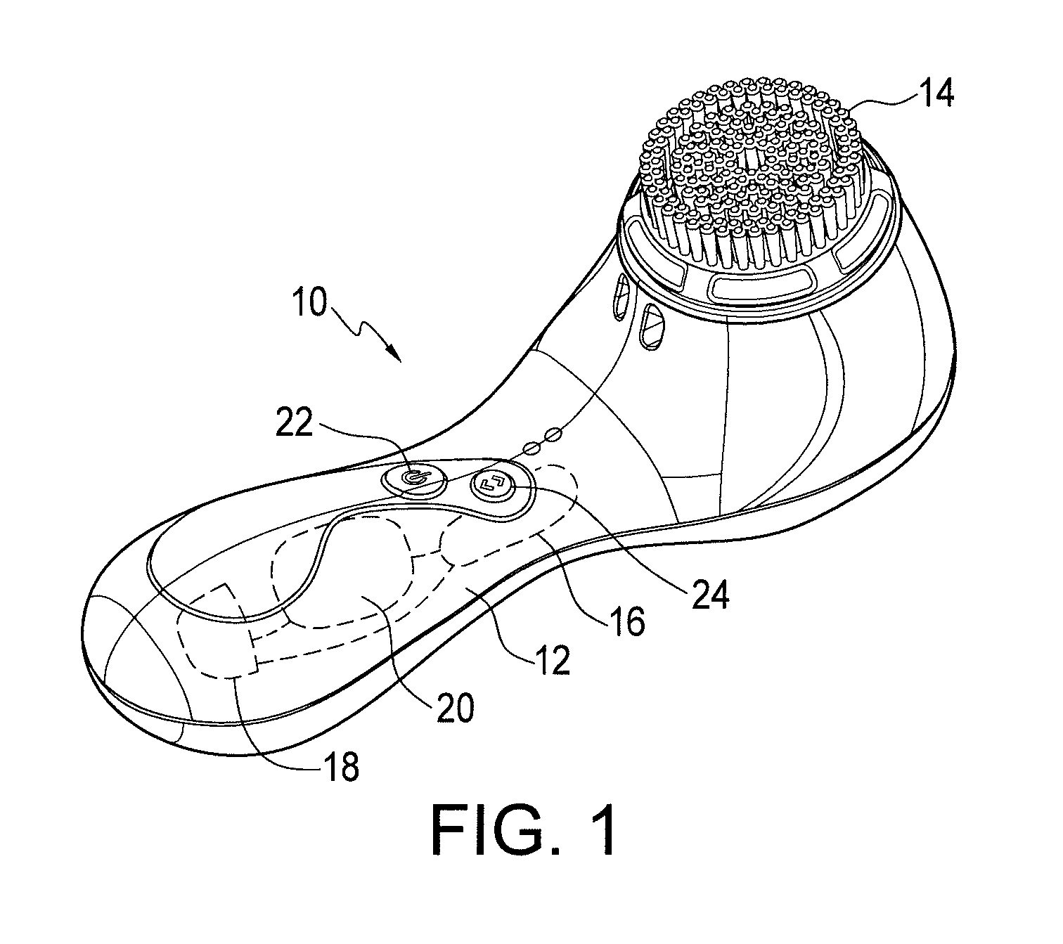
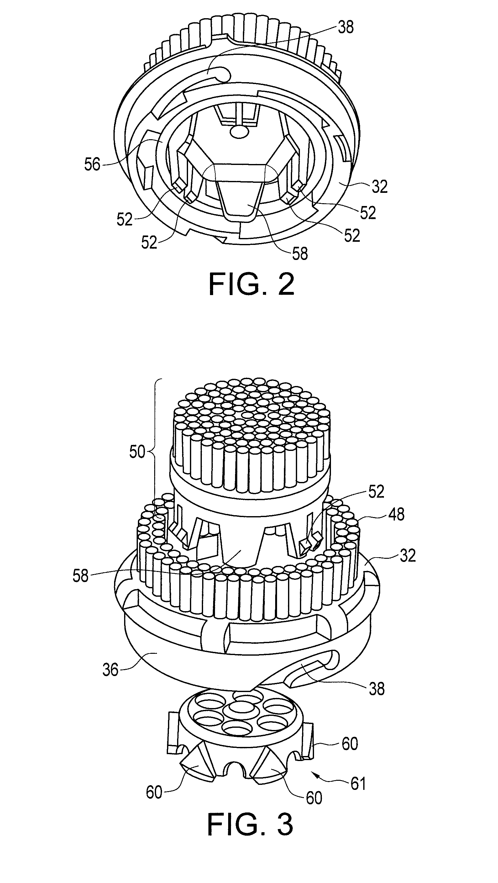
[0015]FIG. 1 shows an electric skin brush appliance generally at 10. The appliance includes a handle 12 and a removable brushhead 14. The arrangement and configuration of the brushhead 14 relative to a drive member of the appliance is shown and described in more detail below. Within handle 12 and represented representationally for clarity are the general operating elements of the appliance, including a drive motor assembly 16, which is powered by a rechargeable battery 18. The operation of the appliance is controlled by a microprocessor / controller 20. The appliance includes an on / off button 22 and a power mode control button 24. The appliance of FIG. 1 is designed to operate at sonic frequencies, typically in the range of 166-186 Hz, oscillating the brushhead portion 14 back and forth rotationally within an amplitude range of 6°-12°. The appliance shown in FIG. 1 is an example of the structure and operation of one skin brush appliance; the structure, operation frequency and oscillat...


PUM


Abstract

An adjusting brushhead includes a base assembly which is removably connectable to an electric skin care appliance. The brushhead also includes an inner brush assembly which oscillates in operation by a drive member with motor action. The brushhead further includes an outer brush assembly which is mounted to the base assembly by mounting elements, permitting the outer brush assembly to move in accordance with facial contours.

Description

TECHNICAL FIELD[0001]This invention relates generally to electric skin care appliances having a moving brushhead, and more particularly concerns such a brushhead which is capable of adjusting to facial contours.BACKGROUND OF THE INVENTION[0002]A conventional oscillating skin care device, such as shown in U.S. Pat. No. 8,484,788, includes a replaceable brush assembly having inner and outer brush portions. The inner brush portion is oscillated at a selected frequency, while the outer brush portion remains fixed in position, with both brush portions having upper surfaces which terminate in a single plane.[0003]Users must reposition the appliance frequently so that the upper surfaces of the brush portions contact the surface of the portion of the face being treated. This can be either difficult or inconvenient at times, so that the overall treatment of the facial area can be compromised.[0004]Accordingly, it is desirable to have a brushhead arrangement capable of effective treatment of ...

Claims


Application Information

Patent Timeline
Patent Type & Authority Patents(United States)
IPC IPC(8): A46B7/08A46B13/02A46B13/00A46B9/02
CPCA46B13/008A46B9/02A46B5/0025A46B13/02A46B2200/1006
Inventor GREZ, JOSEPHMILLER, ZANE BOWMAN ALLEN
Owner LOREAL SA
Why Eureka
Eureka Blog
Learn More