Backhoe log splitter attachment tool

a technology of log splitter and attachment tool, which is applied in the field of machines and devices, can solve the problems of inability to adapt or modify easily, the majority of power-operated log splitters are relatively expensive, and the most commercially available power-operated log splitters are limited. achieve the effect of quick and easy engagement and disengagement of the buck

Active Publication Date: 2016-07-12
NEWMAN JOSEPH E
View PDF22 Cites 4 Cited by
  • Summary
  • Abstract
  • Description
  • Claims
  • Application Information

AI Technical Summary

Benefits of technology

[0029]It is therefore an object of the present invention to provide a log splitter attachment tool or device for use in combination with material moving machines such as a backhoe that can be easily engaged and disengaged from such machine.
[0031]It is a further object of the invention to provide a log splitter attachment device and method of use in combination with a mobile machine such as a backhoe that requires a minimum number of additional working parts and whereby the backhoe can be utilized both to pick up and move and then to split logs while minimizing the amount of manual labor required to operate and load the splitter.
[0036]The present invention is a log splitter tool attachment or mechanism as an accessory to be used with mobile machines having an articulating boom and dipper stick such as a backhoe, which tool can be operably connected either directly to the dipper stick and hydraulic cylinder used to pivot the bucket, or to a quick coupler mechanism used to more quickly and easily engage and disengage a bucket as well as other attachments to the dipper stick and bucket cylinder. The log splitter attachment includes a body section adapted for operably connecting the attachment either directly to the dipper stick or indirectly via a quick coupler mechanism, and a blade section including a cutting or splitting blade which when the tool is secured to the backhoe is facing inwardly with respect to the dipper stick. The blade is also spaced apart and aligned with a stationary thumb or jaw member or accessory secured extending downwardly from the inner side of the dipper stick opposite the blade, which in one embodiment includes a plurality of log engaging knobs or fingers. An operator utilizing the machine controls can operate the boom and dipper stick having the log splitting attachment device of the present invention thereon to pick up and move a log to a desired cutting or stacking location, holding it around the trunk between the thumb and attachment. The log is released and then picked up again on its ends, with one end of the log pressing against the stationary thumb member and with the blade section of the attachment engaging the opposite end of the log. The bucket hydraulic cylinder is then operated to force the blade inwardly on the end of the log, causing it to spread and eventually split into two separate pieces. A cover plate which is secured over the spaced apart fingers of the thumb or jaw member is also provided to aid in holding logs to be cut and further to prevent smaller diameter logs from slipping between such fingers during cutting operations.

Problems solved by technology

However, most of such power-operated log splitters are relatively expensive in that they require an independent framework that is sturdy enough to support a hydraulic system and motor, and that holds the log or wood during cutting, as well as a means for holding and guiding a movable cutting anvil or blade.
In addition, most commercially available power-operated log splitters are limited in that they cannot be easily adapted or modified for other uses, and are bulky and difficult to transport and store.
's splitting attachment is complicated by the need to secure both a splitting wedge and pusher device to the dipper stick and bucket pivot.
A drawback of most known log splitter attachment devices is that they require either the operator or a separate worker to manually lift and load each log to be split into the splitting device.
Thus, weaker individuals will quickly tire of manually lifting each log onto the splitting device, and in addition there is a danger of muscle pulls, logs slipping, and other devices that together present a significant safety hazard.
Another drawback of existing log splitter attachments is that it is difficult to operate the attachment because the visibility of the operator is obscured by the attachment equipment.
However, this still requires a separate lifting and moving operation and then cutting operation, which is both time-consuming and inefficient.
In addition, known splitter attachments are inflexible in that they are not adapted to be secured either directly to a backhoe dipper stick or using a quick-connect mechanism, and furthermore do not take full advantage of existing attachment devices which can be used in combination with the splitter attachment.

Method used


Image

  • Backhoe log splitter attachment tool
  • Backhoe log splitter attachment tool
  • Backhoe log splitter attachment tool

Examples


Embodiment Construction

[0045]The following detailed description is of the best mode or modes of the invention presently contemplated. Such description although detailed and exact to enable those skilled in the art to practice the invention, and by reference to which in connection with the following description and the accompanying drawings one skilled in the art may be advised of the advantages and construction of the invention, is not intended to be understood in a limiting sense, but merely to exemplify the invention, which may be embodied in other specific structure.

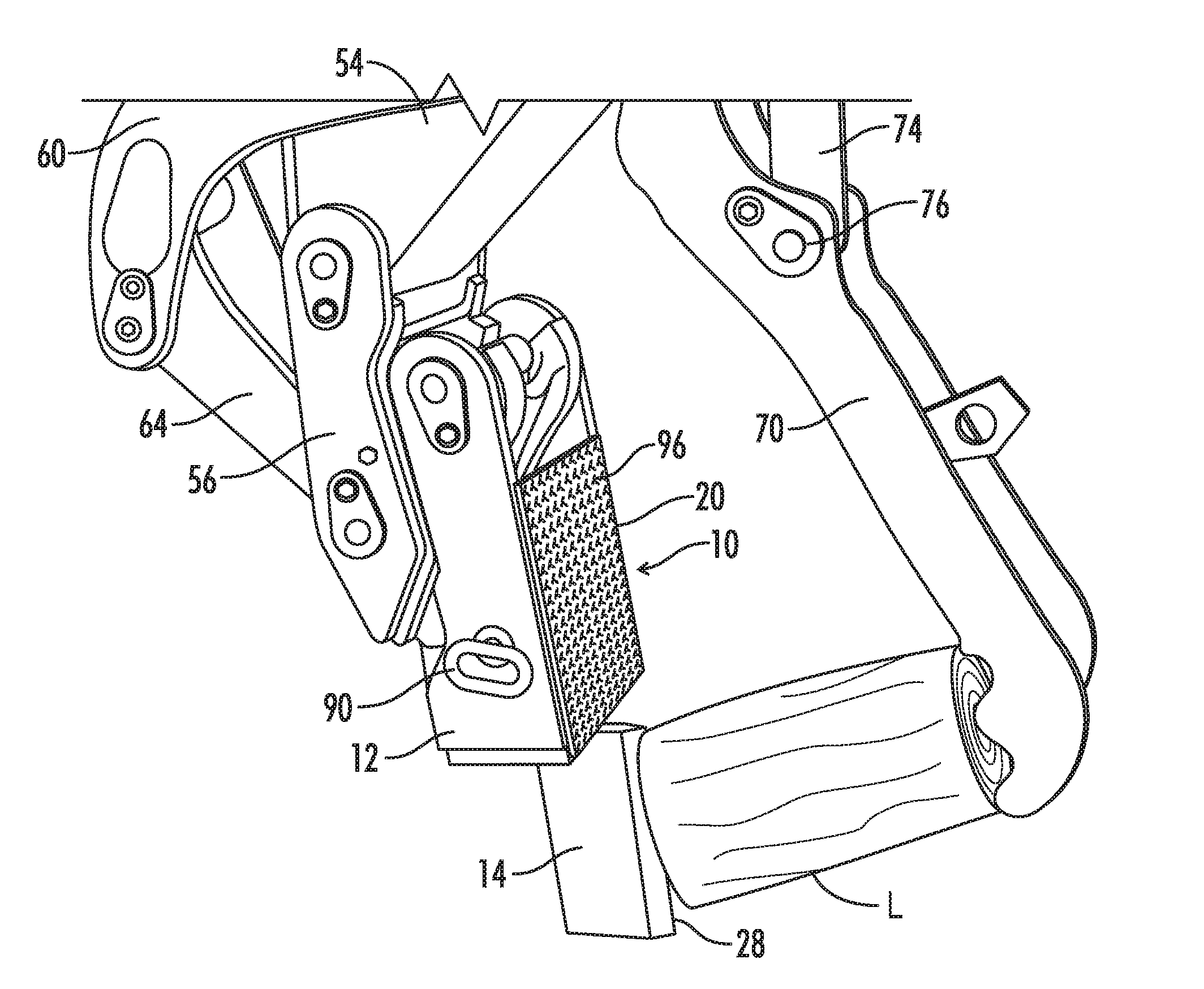
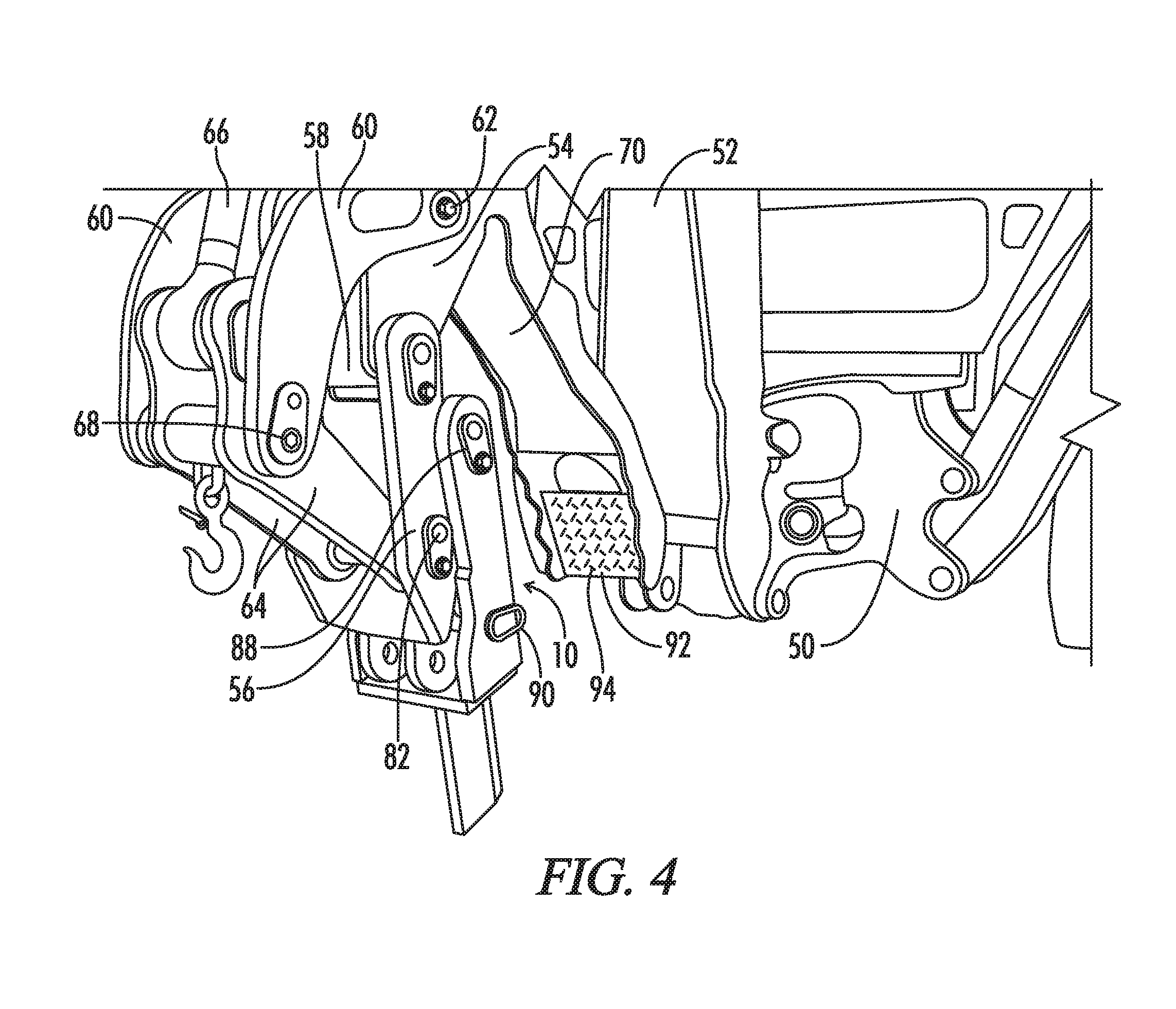
[0046]The log splitting attachment tool or apparatus 10 of the present invention is adapted to be removably secured either directly or indirectly via a quick connect attachment mechanism to the dipper stick of a construction or material moving earthworking machine such as a backhoe machine, having an articulating boom and dipper stick. One such backhoe loader machine available is the 310SE John Deere 4045T Backhoe Loader manufactured by Joh...


PUM


Abstract

A log splitting attachment tool adapted for use in combination with a material moving machine having a boom and dipper stick for lifting and moving as well as splitting logs which tool can alternatively be secured directly to a dipper stick and hydraulic bucket cylinder or to a quick connect mechanism secured thereto.

Description

REFERENCE TO RELATED APPLICATION[0001]This application claims the benefit of U.S. Provisional Application 61 / 487,825 filed on May 19, 2011.BACKGROUND OF THE INVENTION[0002]1. Field of the Invention[0003]The present invention relates generally to machines and devices for splitting logs into smaller sections, and more particularly to hydraulic log splitting machines and devices, and more particularly still to a log splitter attachment tool for use with mobile machines having a hydraulically powered articulating boom and dipper stick such as a backhoe loader, which attachment tool is alternatively connectable to said mobile machine either directly to the dipper stick and bucket hydraulic curl cylinder or indirectly to a quick connect mechanism.[0004]2. Preliminary Discussion and Prior Art[0005]Various log splitting machines are available commercially for purchase, which in general significantly increase the ease, speed and efficiency of the splitting process in comparison to manual spl...

Claims


Application Information

Patent Timeline
Patent Type & Authority Patents(United States)
IPC IPC(8): B27L7/06
CPCB27L7/06B27L7/00
Inventor NEWMAN, JOSEPH E.
Owner NEWMAN JOSEPH E
Why Eureka
Try Eureka