Fiber optic ribbon cable

a fiber optic ribbon and fiber optic technology, applied in the field of fiber optic ribbon cables, can solve the problems of inflexibility, high cost of vcsel technology, and inability to meet the requirements of a single cable, and achieve the effect of decoupling the bend preference of the stack

Active Publication Date: 2016-07-12
CORNING OPTICAL COMM LLC +1
View PDF15 Cites 1 Cited by
  • Summary
  • Abstract
  • Description
  • Claims
  • Application Information

AI Technical Summary

Benefits of technology

[0005]One embodiment relates to a fiber optic ribbon cable, which includes a stack of fiber optic ribbons, strength members surrounding the stack, and a jacket defining an exterior of the cable. The jacket forms a cavity through which extend the stack and the strength members. The stack has a bend preference, but the strength members are positioned around the stack or are flexible in bending such that the strength members, when integrated in the cable, do not have a bend preference. Furthermore, the jacket...

Problems solved by technology

However, costs of transmitters and optical devices for WDM to combine signals at the transmitter and separate them back out at the receiver may be prohibitive for some cost-sensitive applications.
However, VCSEL technology may have reached a maximum speed limit of 25 Gbps per optical channel and there is demand for 40 Gbps and 100 Gbps systems.
However, traditional ribbon cab...

Method used


Image

  • Fiber optic ribbon cable
  • Fiber optic ribbon cable
  • Fiber optic ribbon cable

Examples


Embodiment Construction

[0012]Before turning to the Figures, which illustrate exemplary embodiments in detail, it should be understood that the present inventive and innovative technology is not limited to the details or methodology set forth in the Detailed Description or illustrated in the Figures. For example, as will be understood by those of ordinary skill in the art, features and attributes associated with embodiments shown in one of the Figures may be applied to embodiments shown in others of the Figures.

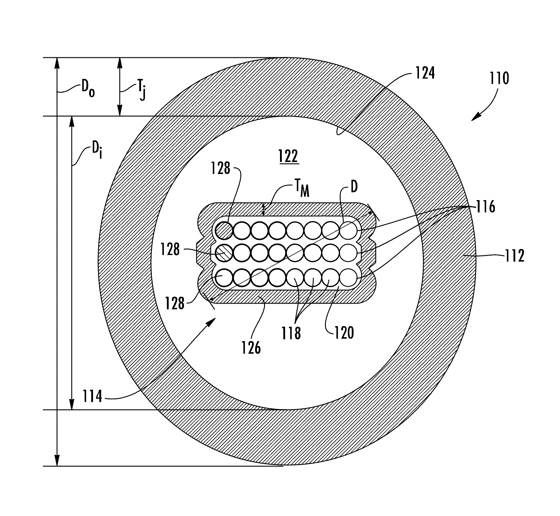
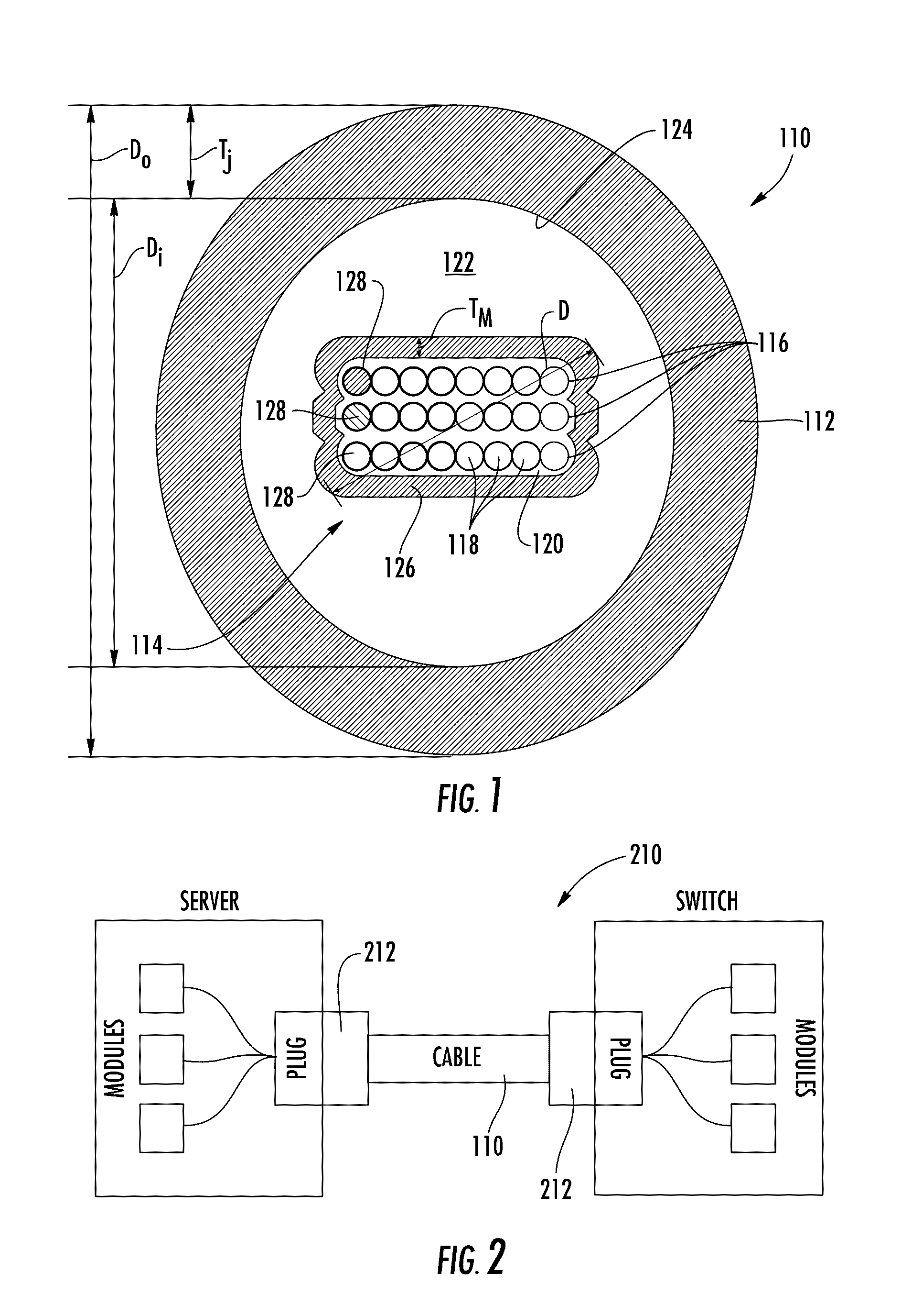
[0013]Referring to FIG. 1, a fiber optic ribbon cable 110 includes a jacket 112 surrounding a stack 114 of fiber optic ribbons 116. According to an exemplary embodiment, the stack 114 of fiber optic ribbons 116 includes at least three fiber optic ribbons 116, where each fiber optic ribbon 116 includes at least eight optical fibers 118 arranged side-by-side and coupled to one another in a common matrix 120, such as an ultra-violet light curable resin (e.g. acrylate).

[0014]Strength members 122, such a...


PUM


Abstract

A fiber optic ribbon cable includes a stack of fiber optic ribbons, strength members surrounding the stack, and a jacket defining an exterior of the cable. The jacket forms a cavity through which the stack and the strength members extend. The stack has a bend preference, but the strength members are positioned around the stack or are flexible in bending such that the strength members do not have a bend preference. Furthermore, the jacket is structured such that the jacket does not have a bend preference. The cavity is sized relative to the stack in order to allow the stack to bend and twist within the cavity with respect to the jacket as the cable bends, facilitating movement of the optical fibers of the fiber optic ribbons to low-stress positions within the cavity and decoupling the bend preference of the stack from transfer to the jacket.

Description

BACKGROUND[0001]Aspects of the present disclosure relate generally to fiber optic cables. More specifically, some aspects of the present disclosure relate to fiber optic cables supporting ribbons of optical fibers, such as for device-interconnection applications in data centers and the like.[0002]Demand for increasing bandwidth of data communication systems has been addressed by various means, such as using wavelength division multiplexing (WDM). However, costs of transmitters and optical devices for WDM to combine signals at the transmitter and separate them back out at the receiver may be prohibitive for some cost-sensitive applications. Another approach to increasing bandwidth has been increasing transmitter speed from 1 gigabits per second (Gbps) to 10 Gbps, and recently to 25 Gbps, with low-cost vertical-cavity surface-emitting lasers (VCSELs). However, VCSEL technology may have reached a maximum speed limit of 25 Gbps per optical channel and there is demand for 40 Gbps and 100...

Claims


Application Information

Patent Timeline
IPC IPC(8): G02B6/44
CPCG02B6/4403G02B6/4433G02B6/4482
Inventor HURLEY, WILLIAM CARLJAMES, KENNETH TODDLUTHER, JAMES PHILLIPRIPUMAREE, RADAWAN
Owner CORNING OPTICAL COMM LLC
Why Eureka
Try Eureka