Methods and apparatuses for control of a wearable transdermal neurostimulator to apply ensemble waveforms

a transdermal electrical stimulation and ensemble waveform technology, applied in the field of non-invasive neuromodulation, can solve the problems of limited system design and delivery of tes waveforms, available system does not permit the user to modulate a predetermined amount, and the current system and methods of tes are lacking, so as to achieve quick and accurate instructions and optimize communication speed, power usage and efficiency.

Active Publication Date: 2016-07-19
THYNC GLOBAL INC
View PDF166 Cites 36 Cited by
  • Summary
  • Abstract
  • Description
  • Claims
  • Application Information

AI Technical Summary

Benefits of technology

[0039]Also described herein are methods of and systems for separately modulating any of the ensemble waveforms described herein, including applying an envelope or scaling signal (which may be herein referred to as an amplitude modulation) to all or, in some variations, one or more portions (e.g., one or more component waveforms) of the ensemble waveform. The envelope is typically a lower frequency (e.g., 1 Hz to 900 Hz, 1 Hz to 300 Hz, 1 Hz to 400 Hz, 1 Hz to 500 Hz, 1 Hz to 600 Hz, 1 Hz to 700 Hz, 1 Hz to 800 Hz, 1 Hz to 1 kHz, etc., and is typically lower than the frequency of the component waveforms that it is modulating) pulsed scaling waveform. The low-frequency pulsed signal (envelope signal or amplitude modulation signal, also referred to as a burst signal) may be a square wave, sawtooth wave, etc., and may have a value of between 1 and 0 (or −1 and 1) so that the resulting signal includes bursts and / or modulated intensities of the higher-frequency component waveforms forming the ensemble waveform. As described in greater detail below, applying this amplitude modulation over even one or a few of the component waveforms forming the ensemble waveform may provide a tremendous advantage both in power efficiency for the system and efficacy for inducing a cognitive and / or physiological effect while potentially reducing or eliminating pain or discomfort associated with stimulation.
[0060]In some variations, the controller is not remote to the processor, but may be part of the same device, and / or connected by one or more transmission lines, e.g., electrical traces, wires, etc. For example, the controller may be part of an integrated electrode assembly and neurostimulator that can be worn by the user. When the controller is remotely located and wirelessly communicates with the neurostimulator apparatus, the communication between the remotely located controller and the processor of the neurostimulator may be one way (e.g., from the remotely located controller to the neurostimulator) or two-way. In general, communication between the two may be specifically encoded (and in some cases may be encrypted), to optimize the speed, power usage and efficiency of the communication between the controller and the processor of the neurostimulator apparatus, to allow the quick and accurate transfer of instructions for stimulation between a controller and a neurostimulator. Although there are numerous ways that these instructions may be encoded and / or processed, described herein are particularly advantageous methods and apparatuses embodying these methods.

Problems solved by technology

Despite the research to date on TES neuromodulation, existing systems and methods for TES are lacking in at least some cases regarding the design and use of effective TES waveforms.
Available systems are limited regarding the design and delivery of TES waveforms.
Moreover, available systems do not permit the user to modulate a predetermined / preconfigured electrical stimulation protocol.
However, the systems and methods described by Brocke are lacking in at least some instances for defining, acquiring, and / or delivering effective TES waveforms to a user.
Such stimulation is not specific to a particular effect (e.g., cognitive effect such as calming or energizing a subject) and may not be universally effective.

Method used


Image

  • Methods and apparatuses for control of a wearable transdermal neurostimulator to apply ensemble waveforms
  • Methods and apparatuses for control of a wearable transdermal neurostimulator to apply ensemble waveforms
  • Methods and apparatuses for control of a wearable transdermal neurostimulator to apply ensemble waveforms

Examples


examples

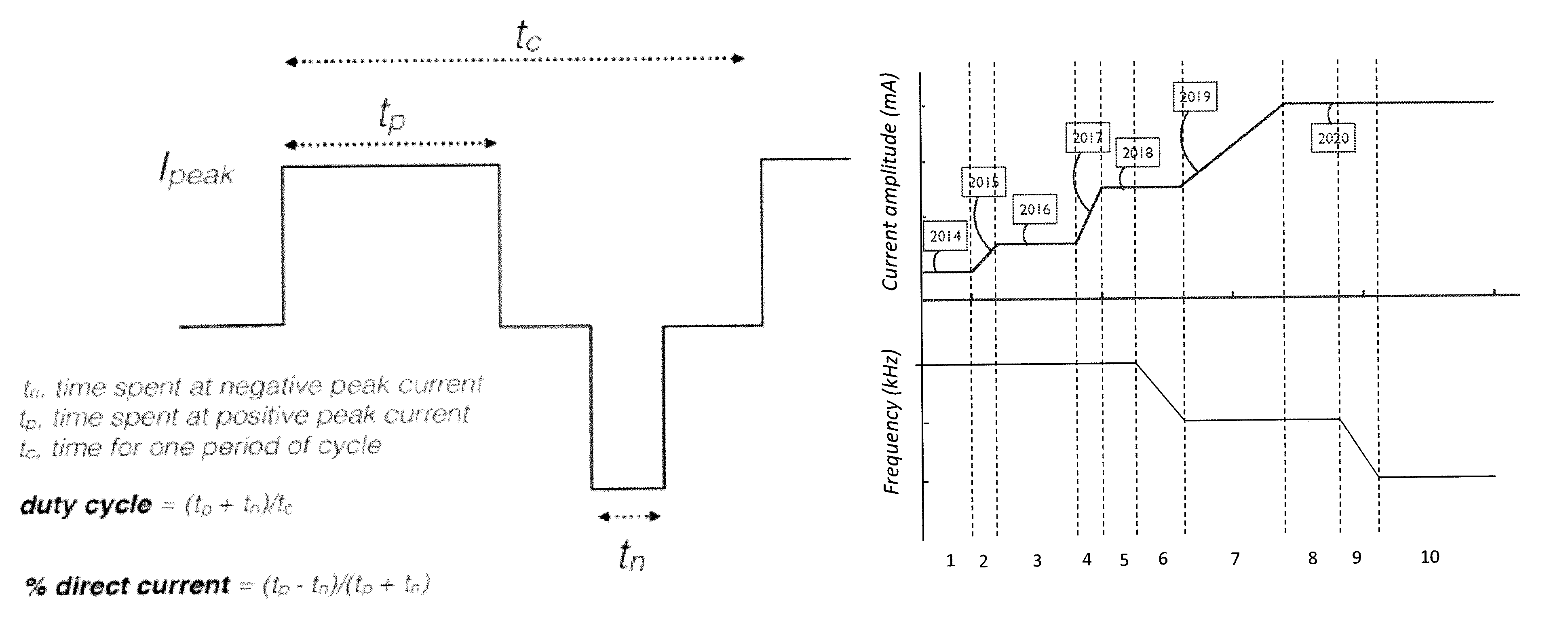
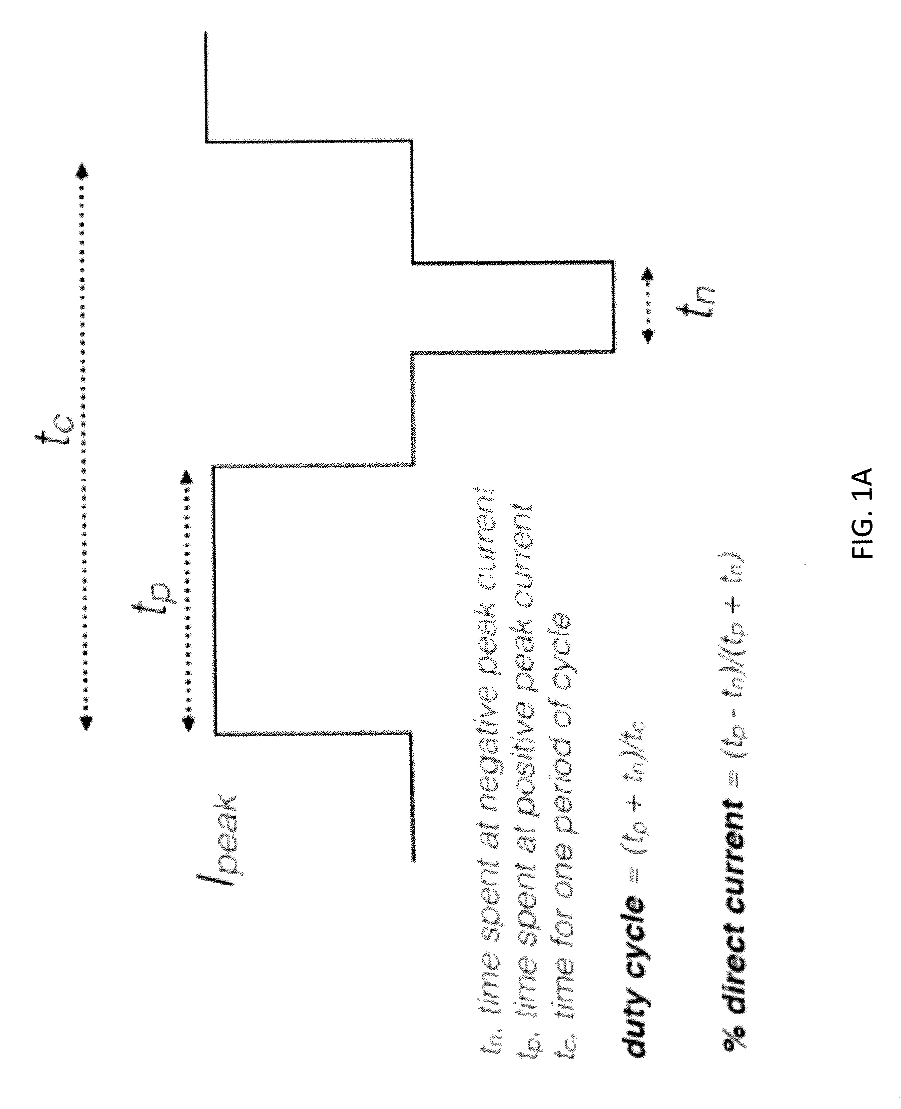
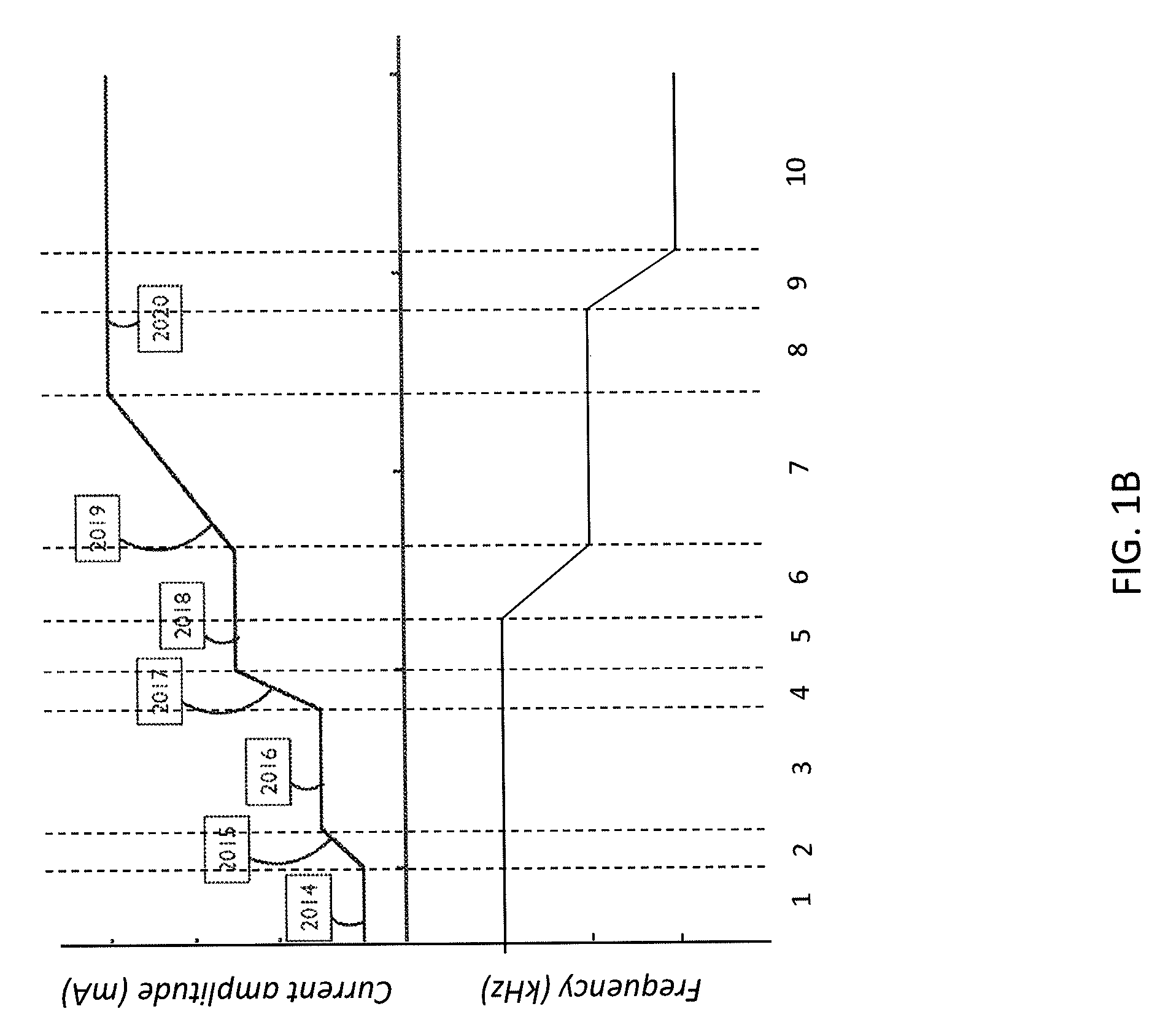
[0171]Three additional examples of parameters for ensemble waveforms are described below. In these examples the waveforms may be implemented in the neurostimulation systems described above and illustrated in FIGS. 3A-3Q. These waveforms may be defined as a vector array including the duration and waveform parameters (frequency that the basic waveform unit is repeated, peak current amplitude, percent charge imbalance of the basic waveform unit, percent duty cycle of the basic waveform unit, and, optionally, capacitive discharge parameters and / or amplitude modulation or burst mode parameters). The basic waveform unit may be defined, or may be set by the system, e.g., as biphasic, square pulses having a predetermined or variable period cycle (i.e., by composing waveforms having chirped pulses).

[0172]Example 1 is shown in FIG. 4A, and is another example of a calm ensemble waveform. The table shown in FIG. 4A lists the waveform parameters for each of the component waveforms. In this examp...


PUM


Abstract

Methods and apparatuses for controlling a wearable neurostimulator from a control apparatus. Described herein are methods and apparatuses for controlling the application of ensemble waveforms using a transdermal electrical stimulation by a neurostimulator having a processor. The controller may provide specifically configured commands to efficiently and accurately control the delivery of an ensemble waveform by the neurostimulator, wherein the ensemble waveform includes a sequence of component biphasic current waveforms in which one or more parameters (such as frequency, current amplitude, percent duty cycle, and percent charge imbalance) vary between sequential component waveforms particularly effective at evoking a desired cognitive state by TES.

Description

CROSS REFERENCE TO RELATED APPLICATIONS[0001]This application claims priority to the following provisional patent applications, each of which is herein incorporated by reference in its entirety: U.S. Provisional Patent Application No. 61 / 994,860, titled “SYSTEMS, DEVICES, AND METHODS FOR TRANSDERMAL ELECTRICAL STIMULATION WAVEFORM DESIGN AND USE,” and filed on May 17, 2014; and U.S. Provisional Patent Application No. 62 / 100,029, titled “METHODS AND APPARATUSES FOR DELIVERY OF ENSEMBLE WAVEFORMS,” and filed on Jan. 5, 2015.INCORPORATION BY REFERENCE[0002]All publications and patent applications mentioned in this specification are herein incorporated by reference in their entirety to the same extent as if each individual publication or patent application was specifically and individually indicated to be incorporated by reference.FIELD[0003]This invention relates generally to methods and apparatuses for noninvasive neuromodulation, and more specifically to transdermal electrical stimul...

Claims


Application Information

Patent Timeline
Patent Type & Authority Patents(United States)
IPC IPC(8): A61N1/372A61N1/36
CPCA61N1/3727A61N1/36025A61N1/36082A61N1/37217A61N1/0456A61N1/36014A61M2021/0072A61M2205/3584A61M2205/505A61N1/0476A61N1/0484A61N1/0492A61N1/36034
Inventor DEMERS, REMIPAL, SUMON K.CHARLESWORTH, JONATHANHAMLIN, JAY FREDERICK
Owner THYNC GLOBAL INC
Why Eureka
Try Eureka