
Voltage control circuit and method for supplying an electrical component with a supply voltage

Active Publication Date: 2008-09-02
INTEL CORP
View PDF6 Cites 21 Cited by
  • Summary
  • Abstract
  • Description
  • Claims
  • Application Information

AI Technical Summary

Benefits of technology

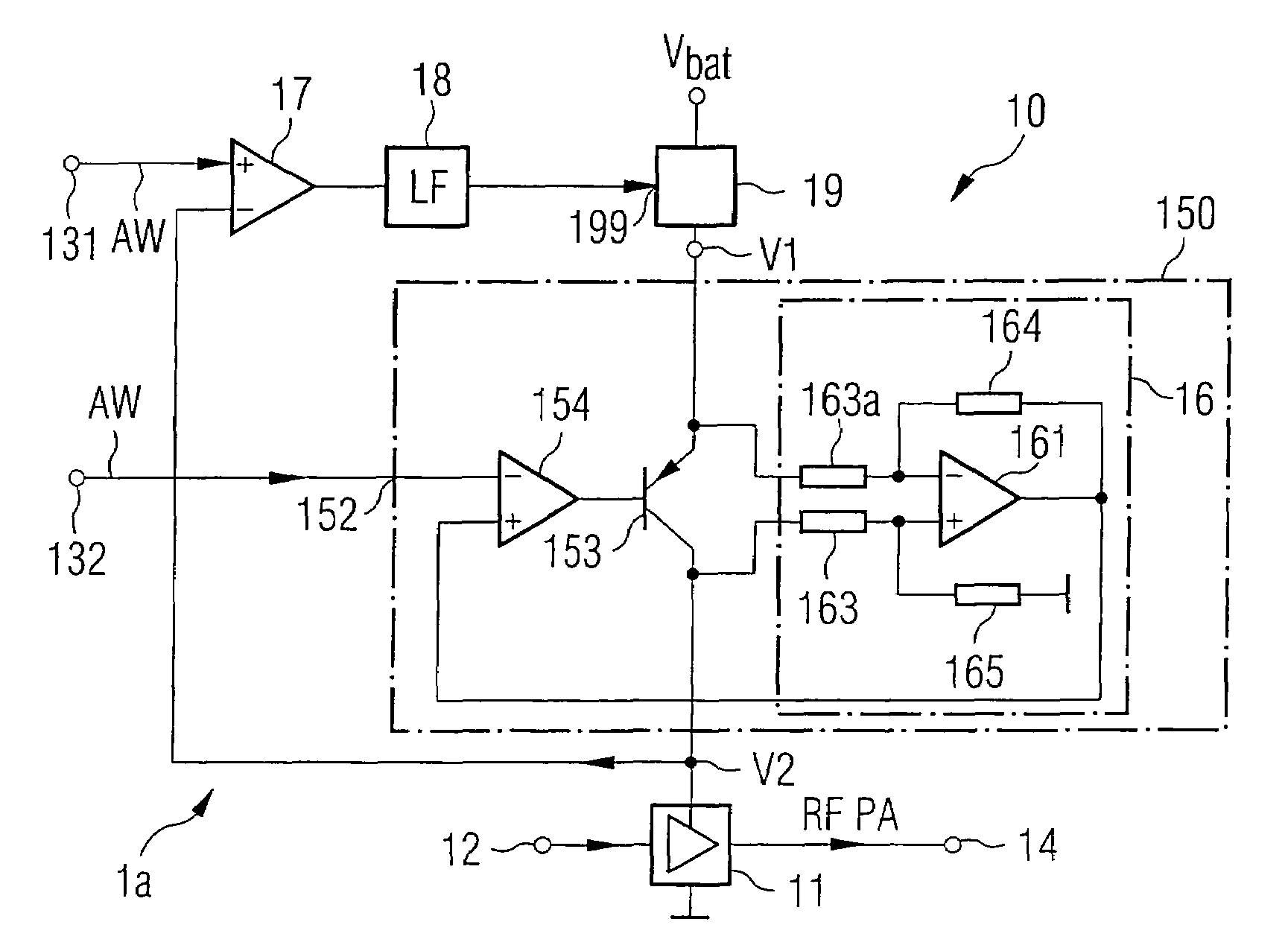
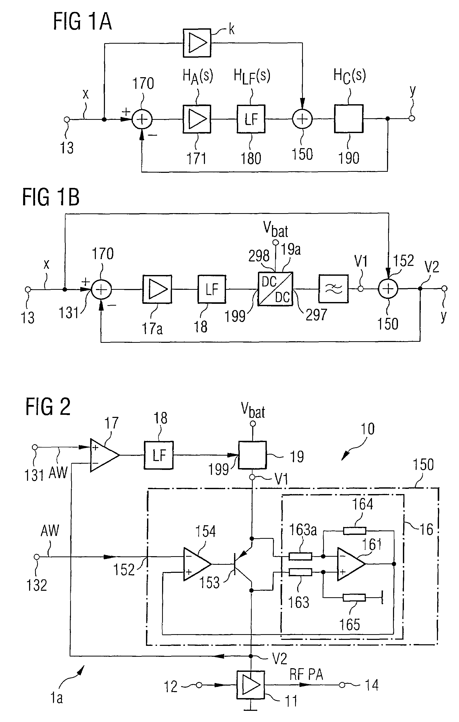
[0013]The first feed element in the voltage control circuit according to the embodiment of the invention corresponds to a low-pass filter element, and the second feed element corresponds to a high-pass filter element. The high-pass and low-pass filter functions which are defined in the control loop inherently complement one another to produce unity, thus ensuring an essentially constant transfer function. This makes it possible to provide a narrowband voltage converter in the voltage control circuit and nevertheless to apply relatively high-frequency voltage control signals to it, for amplitude modulation of the supply voltage. The requirement for the converter is thus reduced, while nevertheless retaining high efficiency. The converter is advantageously in the form of a converter which is operated on a clocked basis.
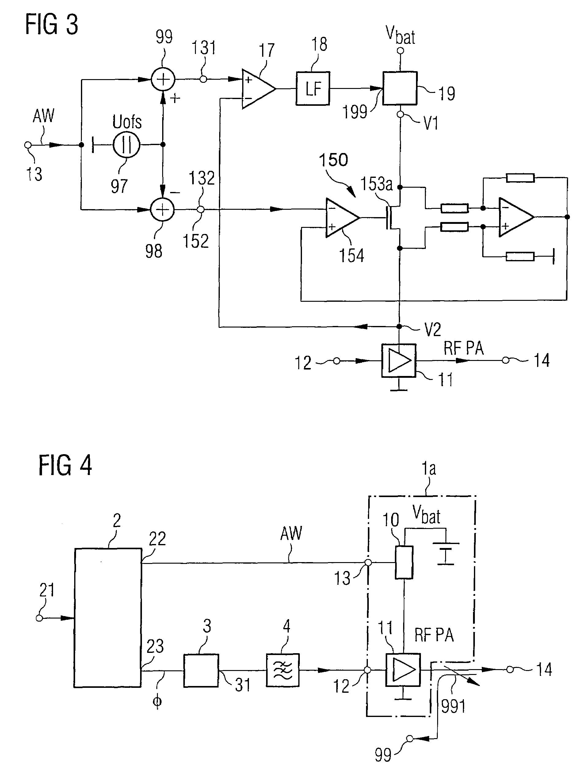
[0020]This embodiment advantageously allows a DC voltage component at one input of the voltage converter or the DC / DC converter within the control loop of the voltage control circuit to be added, which is sufficiently large to avoid saturation of the switched path. The controlled path can thus be operated approximately without any distortion. In order to compensate for this additional DC voltage component, a corresponding signal with the opposite mathematical sign is supplied to the second feed element and thus provides correction with respect to the output of the voltage control circuit. In one advantageous embodiment, the core line of the series regulator can be shifted by suitable definition of the first and second voltage signals, thus also making it possible to achieve an efficiency advantage.

Problems solved by technology

However, this principle has the disadvantage that a relatively large amount of power is consumed uselessly via the series regulator.
Since the amplitude modulation and, in particular, its signal statistics are in fact governed by the mobile communication standard being used, the power losses represent an upper limit on the efficiency of the transmitter.
These two requirements are virtually impossible to combine in all relevant mobile radio systems.
This filtering would have to have a high level of stop-band attenuation, which could be achieved only with major difficulty within the DC / DC converter or the voltage converter, owing to the high switching currents that occur.

Method used


Image

  • Voltage control circuit and method for supplying an electrical component with a supply voltage
  • Voltage control circuit and method for supplying an electrical component with a supply voltage
  • Voltage control circuit and method for supplying an electrical component with a supply voltage

Examples


Embodiment Construction

[0043]In order to minimize the power losses during modulation of the supply voltage of a radio-frequency amplifier, it is possible to use a voltage converter which is preferably in the form of a DC / DC converter. The expression DC / DC converter in the following text is used to mean a circuit which converts a first voltage to a second voltage. In addition, regulation is required in order to stabilize the output voltage of the converter. The output side of the converter is connected to the supply input of the amplifier.

[0044]DC / DC converters are operated on a clocked basis, and convert one voltage, for example from a battery, to a second voltage. The output voltage which is emitted from the converter may in this case be less than the input voltage (step-down converter) or greater than the input voltage (boost converter). The conversion ratio is in this case supplied to the converter by means of an amplitude modulation word. In the case of radio-frequency amplitude modulation, as is requ...


PUM


Abstract

A voltage control circuit is proposed, having an input for supplying a voltage control signal and having an output for production of a supply voltage. The voltage control circuit contains a control loop with a DC / DC converter arranged between a first node and a second node. The first node is designed to emit the difference between signals which are applied on the input side. The second feed node is designed to emit the sum of the applied signals. The first and the second feed nodes provide two point modulation with the DC / DC converter within the control loop of the voltage control circuit. In this case, a signal which is applied on the input side is split into a radio frequency component and a low frequency component. The processing of the low frequency component in the DC / DC converter reduces the requirements for the switching frequencies for the DC / DC converter, increases the efficiency of the voltage control circuit, and reduces the power losses.

Description

FIELD OF THE INVENTION[0001]The invention relates to a voltage control circuit. The invention furthermore relates to a method for supplying an electrical component with a supply voltage.BACKGROUND OF THE INVENTION[0002]Mobile communication appliances are increasingly making use of radio-frequency transmission architectures which apply the amplitude variation that is required for modulation of the payload data to the radio-frequency output signal at the output stage of the transmission path. The expression amplitude variation is used in this context not only for high-speed amplitude modulation with respect to the modulation type used for the payload data but also for the relatively slow variation of an output level setting.[0003]Frequently, phase modulation is first of all carried out in transmission paths as a function of the modulation type used and of the data to be transmitted on the transmission signal, with the amplitude of a phase-modulated transmission signal then being varie...

Claims


Application Information

Patent Timeline
IPC IPC(8): H03F3/38H03G3/20
CPCH03G3/3047H03G3/3042H02M3/158H02M2001/0045H02M1/0045
Inventor HERZINGER, STEFANKRAUT, GUNTHER
Owner INTEL CORP
Learn More