Scalable wavelength shifted laser source and method

a wavelength shift and laser source technology, applied in the direction of laser details, instruments, active medium shape and construction, etc., can solve the problems of significant drawbacks, limited output power, and restricted wavelength of operation, and achieve the effect of convenient scalable to higher powers and facilitate transmission through the atmospher

Active Publication Date: 2005-07-21
NORTHROP GRUMMAN SYST CORP
View PDF10 Cites 19 Cited by
  • Summary
  • Abstract
  • Description
  • Claims
  • Application Information

AI Technical Summary

Benefits of technology

[0005] The present invention resides in a scalable high power laser source of which the output wavelength can be shifted to a desired region, such as an eyesafe wavelength region beyond 1500 nm or a desired region that facilitates transmission through the atmosphere. Briefly, and in general terms, the invention defined in terms of a laser architecture comprises an array of laser fiber amplifiers; a master oscillator generating a pump beam at a first frequency; means for coupling the pump beam into each of the laser fiber amplifiers; means for generating a secondary beam at a second frequency; an array of optical parametric amplifiers; means for coupling amplified pump beams from the laser fiber amplifiers into respective optical parametric amplifiers; and means for coupling the secondary beam into each of the optical para

Problems solved by technology

These laser sources are needed for a variety of applications, both military and commercial, but output power is significantly limited with current MWIR technology.
Phased arrays of high power fiber amplifiers have been demonstrated or proposed but have significant drawbacks.
A critical limitation is that the wavelength of operation is restricted by the gain bandwidth of the rare earth dopant used in the core of the fiber amplifiers.
Unfortunately, this is a spectral region in which the eye is quite vulnerable to perm

Method used


Image

  • Scalable wavelength shifted laser source and method
  • Scalable wavelength shifted laser source and method
  • Scalable wavelength shifted laser source and method

Examples


Embodiment Construction

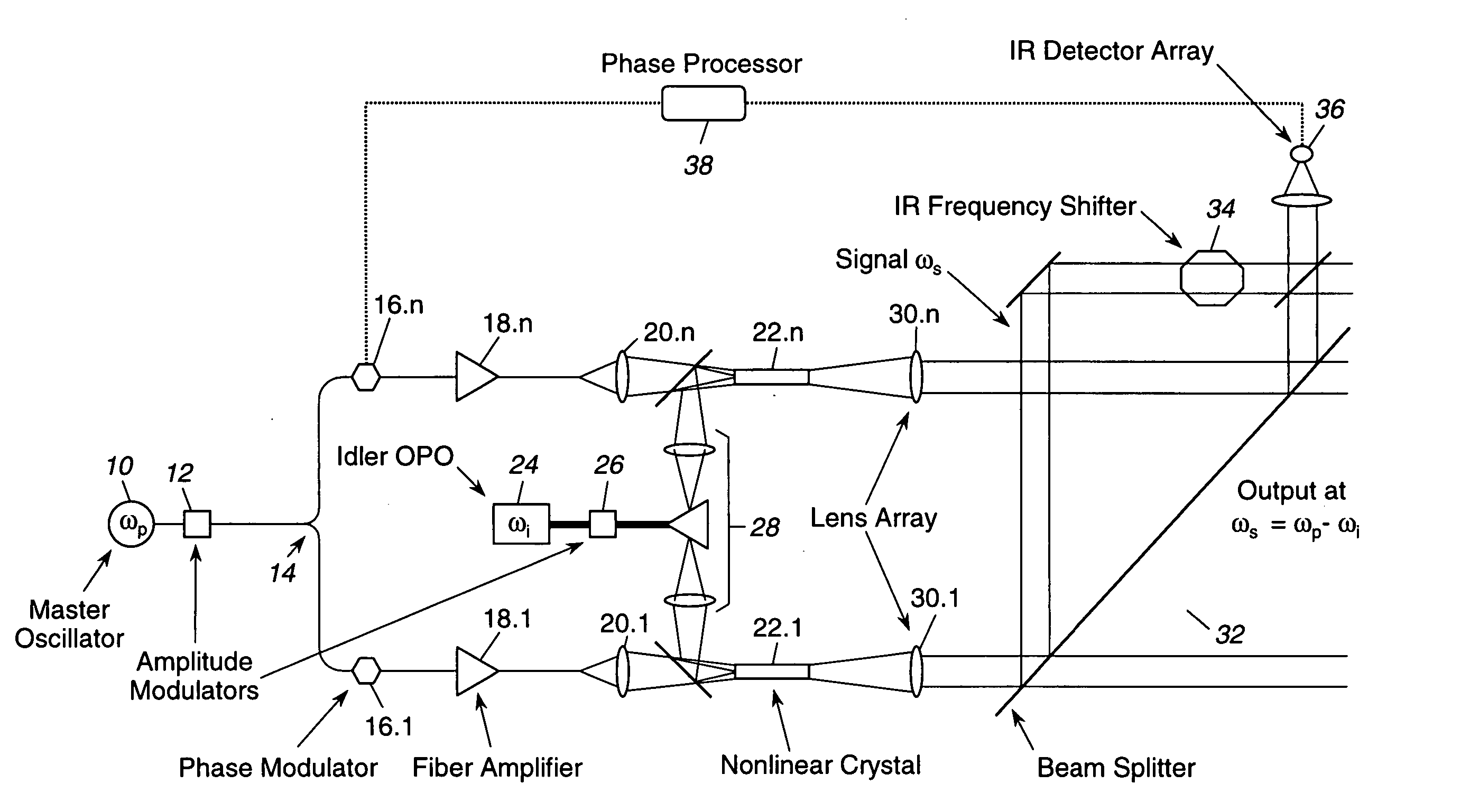
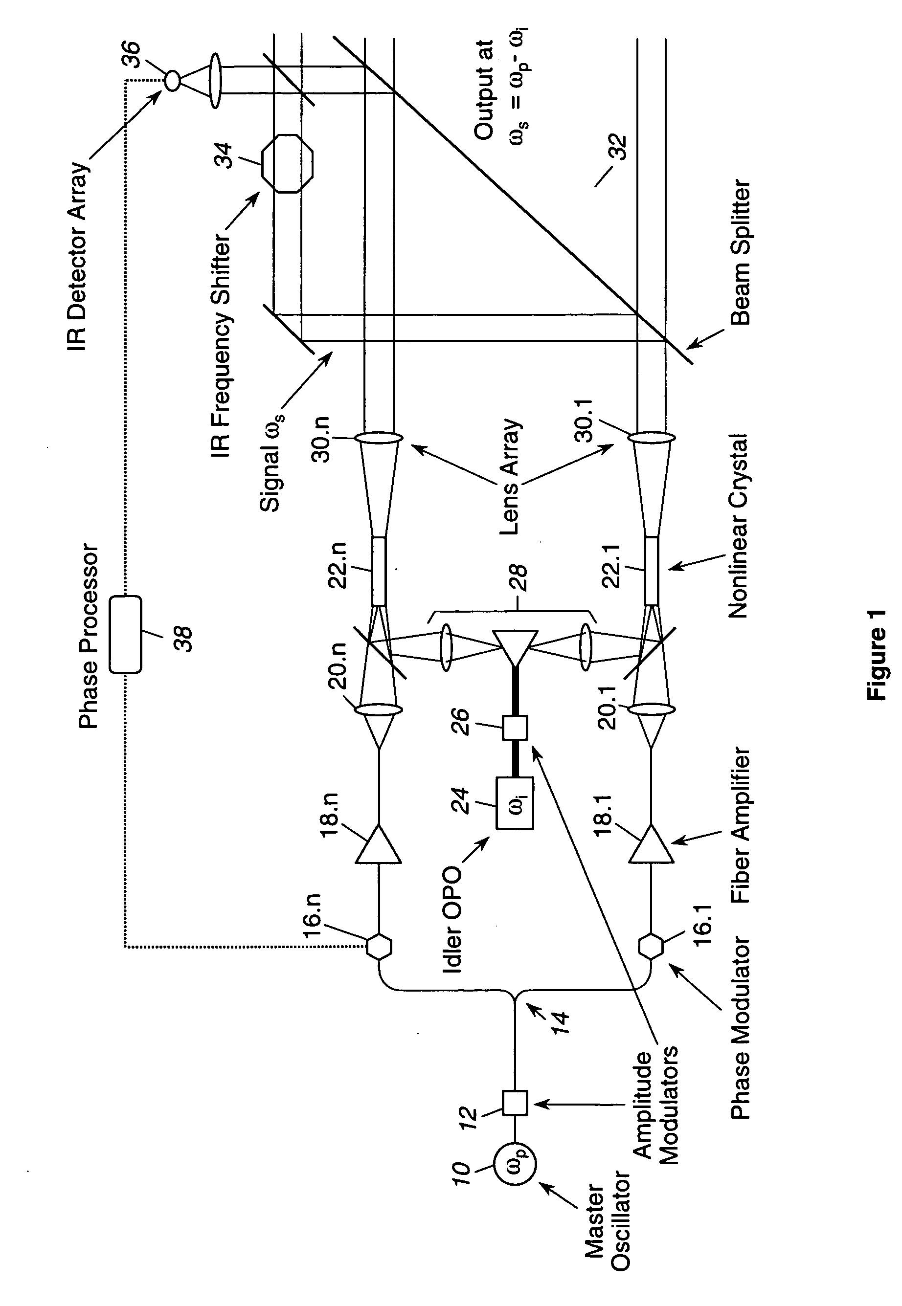
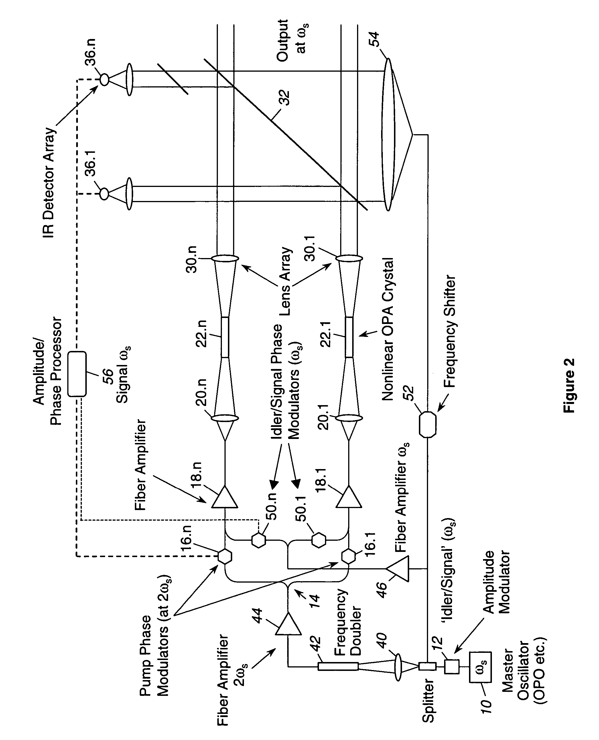
[0013] As shown in the drawings for purposes of illustration, the present invention is concerned with a laser source architecture that is both scalable to high powers and is wavelength selectable, independent of the constraints normally imposed by properties of rare earth elements used in fiber amplifiers. In the past, arrays of fiber amplifiers have produced outputs that, although scalable to higher powers, have been restricted in wavelength by the gain bandwidth inherently associated with the fiber core materials. For most efficient designs, this gain bandwidth falls in the region 1000 nm to 1100 nm, which is unfortunately not a desirable wavelength range from the standpoint of eye safety.

[0014] In accordance with the invention, an array architecture is configured to provide output at a desired wavelength that is not restricted by the fiber amplifier gain bandwidth. The output is easily scalable to high powers without adversely affecting the efficiency of the device or the beam q...


PUM


Abstract

A laser array architecture scalable to very high powers by fiber amplifiers, but in which the output wavelength is selectable, and not restricted by the wavelengths usually inherent in the choice of fiber materials. A pump beam at a first frequency is amplified in the fiber amplifier array and is mixed with a secondary beam at a second frequency to yield a frequency difference signal from each of an array of optical parametric amplifiers. A phase detection and correction system maintains the array of outputs from the amplifiers in phase coherency, resulting in a high power output at the desired wavelength. A degenerate form of the architecture is disclosed in an alternate embodiment, and a third embodiment employs dual wavelength fiber amplifiers to obtain an output at a desired difference frequency.

Description

BACKGROUND OF THE INVENTION [0001] This invention relates generally to high power laser sources and, more particularly, to midwave infrared (MWIR) high power laser sources. These laser sources are needed for a variety of applications, both military and commercial, but output power is significantly limited with current MWIR technology. Midwave infrared radiation is typically defined as having a wavelength between 2.5 to 6 μm. Near infrared (NIR) radiation has a wavelength between visible red and the midwave IR range, i.e., about 0.7 to 2.5 μm. [0002] Phased arrays of high power fiber amplifiers have been demonstrated or proposed but have significant drawbacks. In a typical prior art approach, output from a master oscillator (MO) is distributed to an array of high power fiber amplifiers pumped by laser diode arrays. The output beams from the fiber amplifiers are combined in a closely packed lens array to form the output beam. A sample of each output beam is compared on a detector arra...

Claims


Application Information

Patent Timeline
IPC IPC(8): G02F1/37H01S3/067H01S3/10H01S3/108H01S3/23H01S3/30
CPCG02F1/3534H01S3/06754H01S3/2383H01S3/10023H01S3/1083H01S3/10015H01S3/0092H01S3/1307H01S3/1305
Inventor RICE, ROBERT R.WICKHAM, MICHAEL G.CHEUNG, ERIC C. T.KOMINE, HIROSHIROTHENBERG, JOSHUA E.
Owner NORTHROP GRUMMAN SYST CORP
Why Eureka
Try Eureka