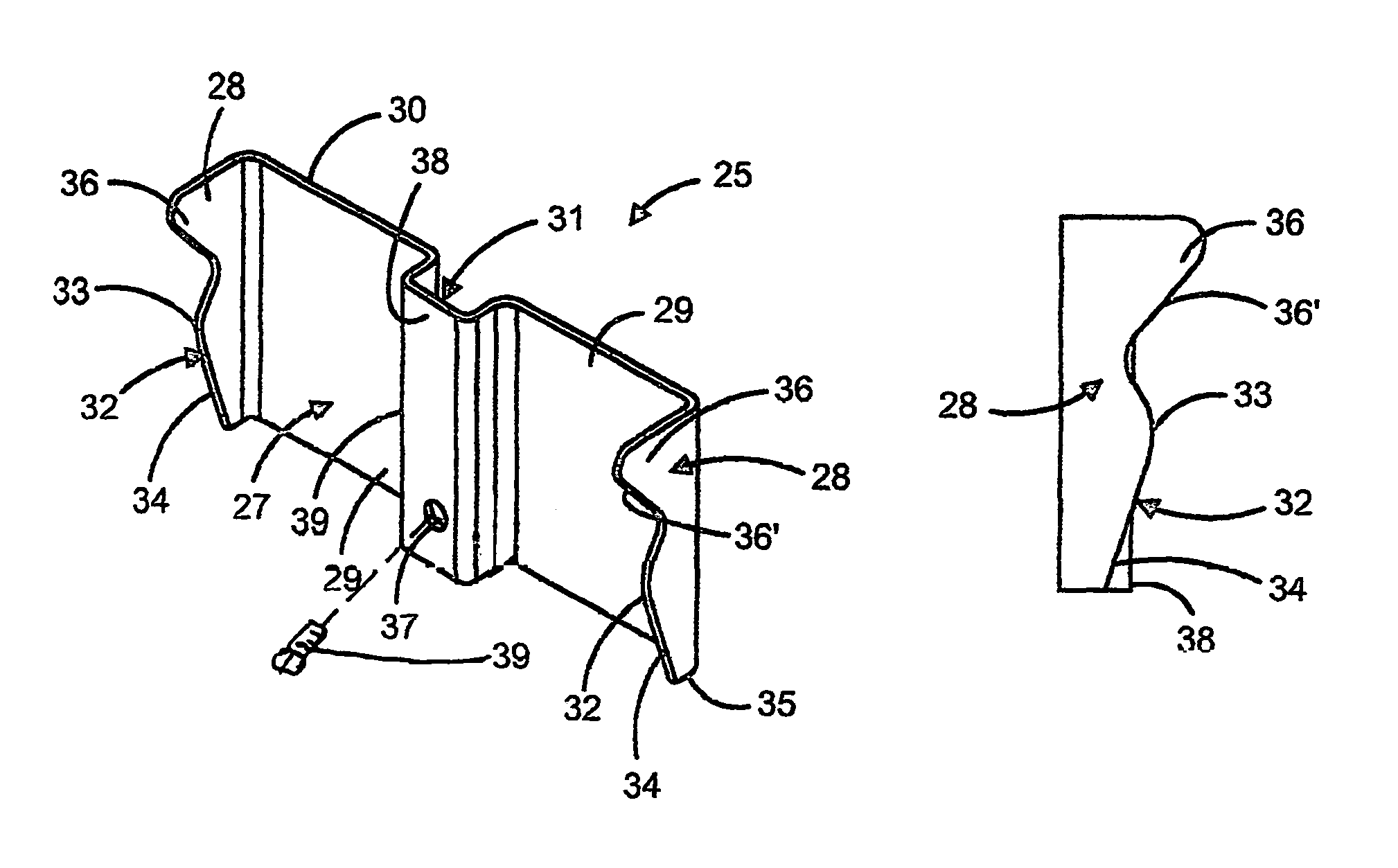
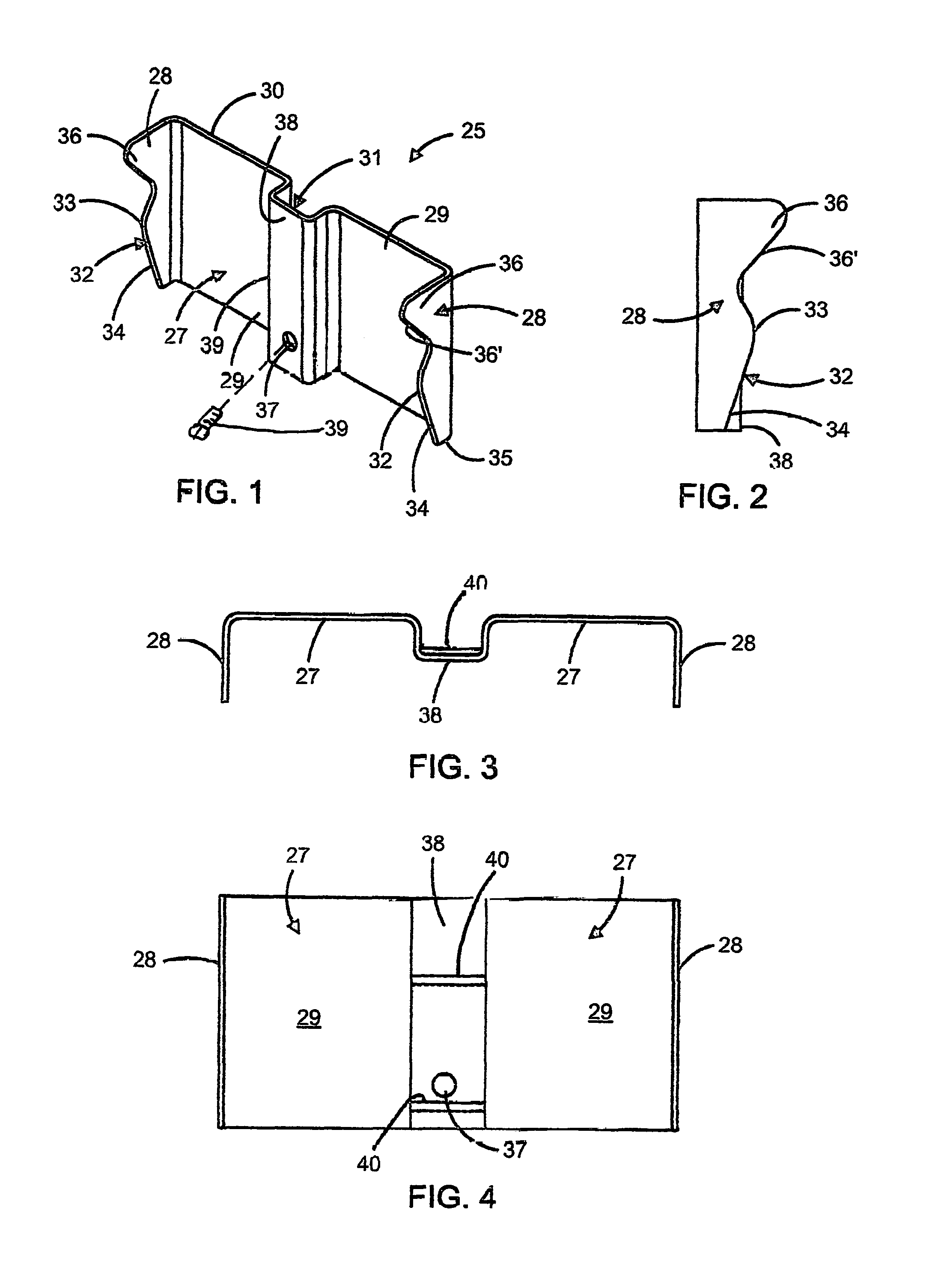
Pressure clamp adapter for mounting a thermistor on a thermostat control bracket

a technology of thermostat control bracket and clamp adapter, which is applied in the direction of explosion-operated switches, bottling operations, building scaffolds, etc., can solve the problem of gap between the temperature sensor and the thermostat control devi

Active Publication Date: 2016-07-19
GIANT FACTORIES
View PDF14 Cites 5 Cited by
  • Summary
  • Abstract
  • Description
  • Claims
  • Application Information

AI Technical Summary

Problems solved by technology

Because such thermostat control devices are not in direct contact with the wall of the water tank there exists a gap between the temperature sensor of the thermostat control device and the actual temperature of the water inside the tank in the vicinity of the thermostat.

Method used


Image

  • Pressure clamp adapter for mounting a thermistor on a thermostat control bracket
  • Pressure clamp adapter for mounting a thermistor on a thermostat control bracket
  • Pressure clamp adapter for mounting a thermistor on a thermostat control bracket

Examples


Embodiment Construction

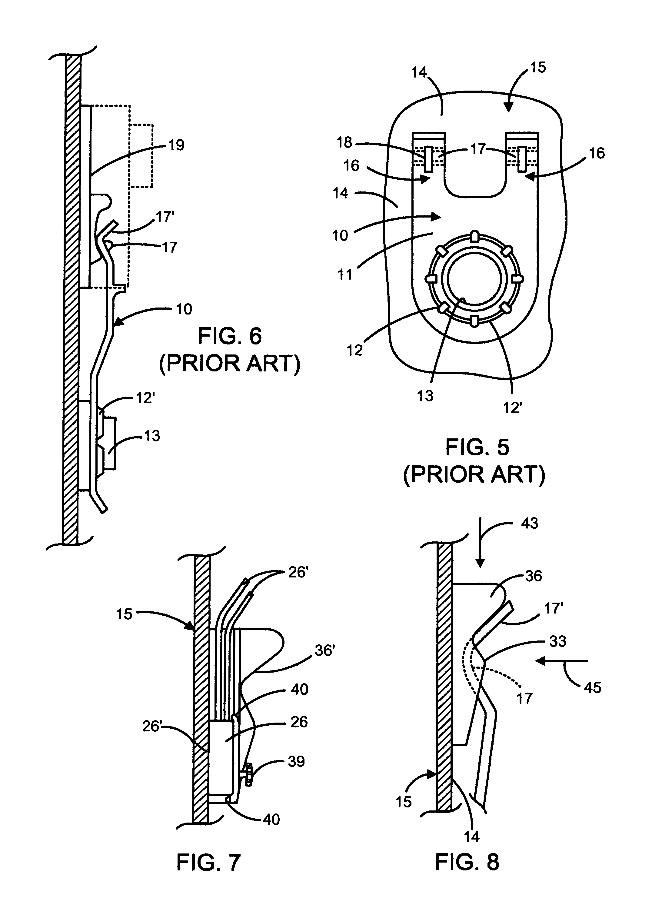
[0023]Referring now to the drawings and more particularly to FIGS. 5 and 6, there is shown an existing prior art thermostat control support bracket 10 having a main body 11 which is provided in a lower region thereof with a circular opening 12 having bent leaves 12′ thereabout to force fit the support bracket 10 about a tank spud 13 projecting from an outer wall 14 of a hot water tank 15 of an electric water heater at different levels, as is well known in the art. A resistive heating element (not shown) is usually secured to the spud 13 and projects in the interior of the tank to heat water therein.

[0024]The thermostat control support bracket 10 is formed from spring steel material, such as stainless steel, and has a pair of upwardly extending spaced-apart legs 16 with each leg having a bight formation 17 at an upper end thereof. A connecting slot 18 is provide in the bight formation 17 for connection to thermostat support bracket 19 which is mounted against the outer surface of the...


PUM


Abstract

A pressure clamp adapter for mounting a thermistor on an existing thermostat control support bracket secured to a hot water tank spud is described. It comprises a thermistor bracket having a rear wall with opposed transverse projecting connecting arm formations extending from an outer surface of the rear wall. A cavity is formed from the rear surface of the rear wall to form a housing shaped to receive a thermistor therein. A passage communicates with the cavity. Each of the connecting arm formations is adapted for removable attachment to a pair of upwardly projecting legs of the thermostat control support bracket.

Description

BACKGROUND OF THE INVENTION[0001]The present invention relates to a pressure clamp adapter for mounting a thermistor on an existing thermostat control support bracket.[0002]Thermostat control devices for electric water heaters have been mounted for many years on support brackets which are attached to the spuds secured to the tank of the water heater. An example of such a support bracket is described in U.S. Pat. No. 4,399,971. These spuds provide for the removable connection of the resistive heating elements. The support bracket is formed from spring steel material and has a spud connecting aperture and a pair of upstanding spring arms each having a bight formation at an outer end for clamping a support of the thermostat control device against the water tank. The thermostat control device is mounted on the support and in close proximity to the tank outer wall whereby to sense the temperature in that region. A mechanical potentiometer is provided on the control thermostat device to m...

Claims


Application Information

Patent Timeline
Patent Type & Authority Patents(United States)
IPC IPC(8): H01H37/04F24H9/20F16B2/24F21V35/00E04G5/06G01D11/30E04G3/00B67B5/06B44D3/12A47K5/00A47K1/00A47G29/24A47G29/18A47B96/06H01H39/00F16L3/08F21V21/00
CPCF24H9/2021F16B2/245F24H9/20F24H9/2007G01D11/305F24H15/37
Inventor LESAGE, CLAUDE
Owner GIANT FACTORIES
Why Eureka
Try Eureka