Gas sensor with thermal measurement compensation

a technology of thermal measurement compensation and gas sensor, which is applied in the direction of instruments, specific gravity measurement, and fluid analysis using sonic/ultrasonic/infrasonic waves. it can solve the problems of narrow limit of specified accuracy of many gas detectors and difficult maintenan

Active Publication Date: 2016-07-19
VERIS INDS
View PDF37 Cites 9 Cited by
  • Summary
  • Abstract
  • Description
  • Claims
  • Application Information

AI Technical Summary

Problems solved by technology

Many gas detectors have narrow limits on the specified accuracy, such as within a range of 2% accuracy, which is difficult to maintain in many operating environments especially with temperature variations.

Method used


Image

  • Gas sensor with thermal measurement compensation
  • Gas sensor with thermal measurement compensation
  • Gas sensor with thermal measurement compensation

Examples


Embodiment Construction

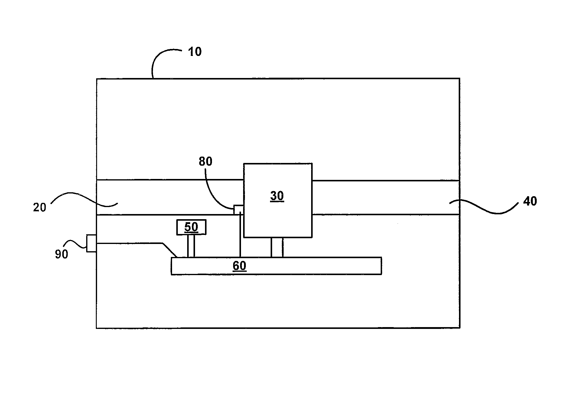
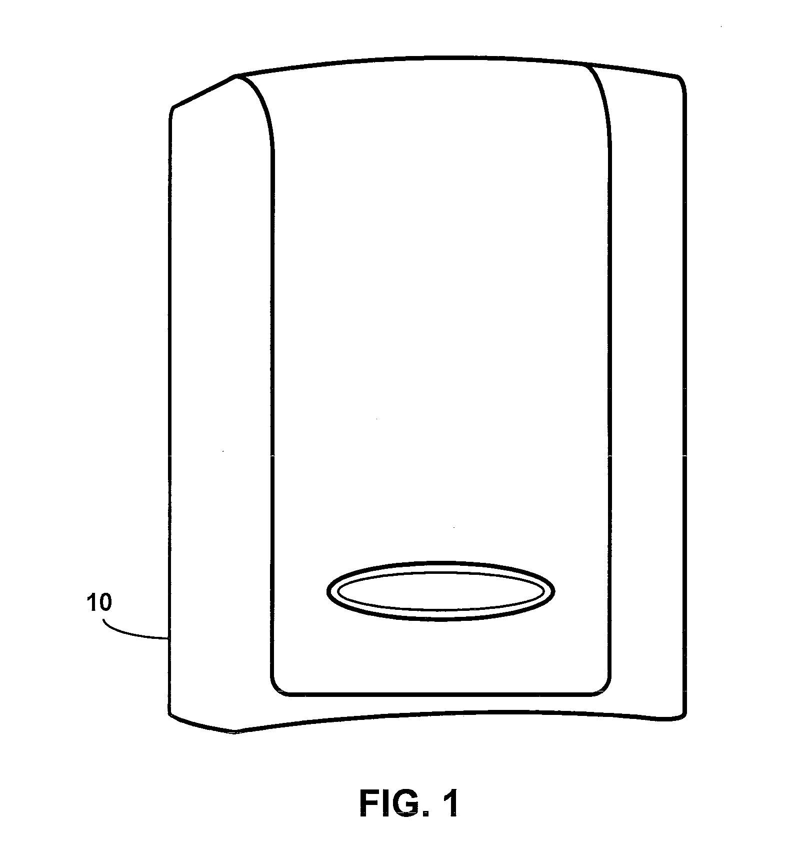
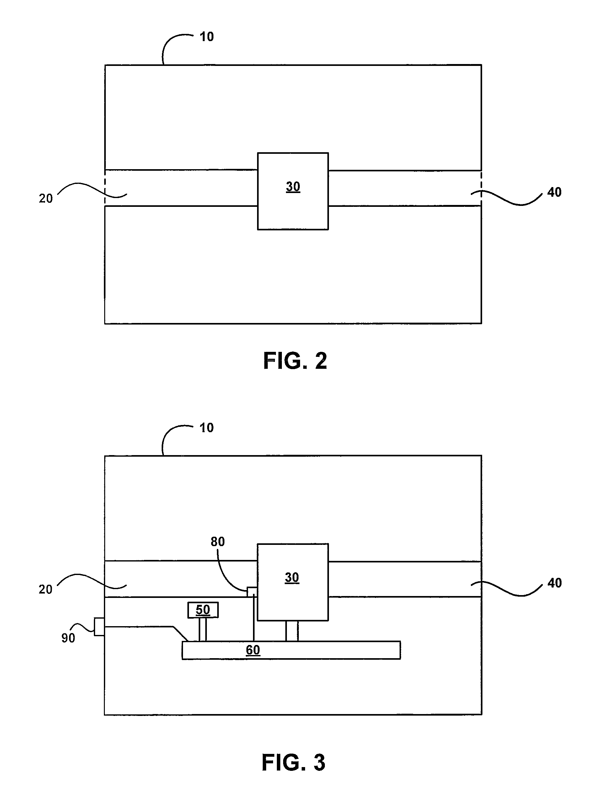
[0011]Referring to FIG. 1, a gas detecting device for the measurement of gases in an environment is positioned within a housing 10. Referring also to FIG. 2, the gas housing includes an air intake passage 20 that directs gas to a gas sensing device 30. The gas sensing device 30 may be a electrochemical device or any other suitable device to sense gas levels of a particular gas, such as for example CO2. The gas passing through or otherwise in communication with the gas sensing device 30 passes through the air outtake passage 40 that directs gas out of the housing 10.

[0012]Referring to FIG. 3, in many environments it is desirable to measure the gas at a relatively consistent temperature, therefore one or more heated components 50 may be in thermal communication with the gas passing through the air intake passage 20 and supported by a circuit board 60. Referring also to FIG. 4, the circuit board 60 may also support a gas sensor 120, a microcontroller 100, a battery (or other power sour...


PUM

PropertyMeasurementUnit
volumeaaaaaaaaaa
temperatureaaaaaaaaaa
molar concentrationaaaaaaaaaa

Abstract

A gas sensing device that includes differential temperature compensation.

Description

CROSS-REFERENCE TO RELATED APPLICATIONS[0001]This application claims the benefit of U.S. Provisional App. No. 61 / 761,404, filed Feb. 6, 2013.BACKGROUND OF THE INVENTION[0002]The present invention relates generally to a gas sensor with thermal measurement compensation.[0003]A gas detector is a device which detects the presence of a gas within an area, often as part of a safety system. Upon detecting a gas leak the system may be used to interface with a control system so that appropriate action may be taken, such as shutting down the gas leak or otherwise sounding an alarm.[0004]Gas detectors typically measure the concentration of a particular gas using a sensing device, such as a gas sensing module. The gas sensing module provides an output to a microcontroller, which typically sends an alarm signal to a control system if the gas level exceeds some threshold level. Many gas detectors have narrow limits on the specified accuracy, such as within a range of 2% accuracy, which is difficu...

Claims


Application Information

Patent Timeline
Patent Type & Authority Patents(United States)
IPC IPC(8): G01N7/00G01N29/02G01N25/00G01N9/00G01N33/00
CPCG01N33/0016G01N33/004
Inventor SHELEY, JOHN HANSON
Owner VERIS INDS
Why Eureka
Try Eureka