Electrostatic ion mirrors

a technology of electrostatic ion mirrors and ion mirrors, applied in the field of electrostatic traps and multi-reflecting timeofflight mass spectrometers, can solve the problems of limiting the ability of forming short ion packets in the ion source, limiting the ability of forming proper field in the reflecting region, and the range of energy focusing stills

Active Publication Date: 2016-07-19
LECO CORPORATION
View PDF17 Cites 23 Cited by
  • Summary
  • Abstract
  • Description
  • Claims
  • Application Information

AI Technical Summary

Benefits of technology

[0014]The inventors have realized that a higher order time-per-energy focusing by grid-free ion mirrors results from a smoother field distribution in the retarding field region, which in turn includes sufficient penetration—at least one tenth of electrostatic potentials of surrounding electrodes into vicinity of the ion turning point. By setting such criteria and in simulations the inventors found that the energy tolerance of ion mirrors can be increased up to at least 18% (compared to 8% in prior art mirrors) at resolving power above 100,000 and time-per-energy focusing can be brought to the fourth or even higher-order compensation by using a combination of at least three electrodes with distinct retarding potentials and at least one electrode with accelerating potential (not accounting electrodes of drift region) and by satisfying particular relations between electrode sizes and potentials.
[0017]The inventors further realized that high isochronicity is the result of sufficient penetration of electrostatic fields from at least three electrodes to provide smooth distribution of electrostatic field with monotonous behavior of potential, electric field and their higher derivatives. This appears to be a (though not sufficient alone) condition for high order isochronicity.
[0026]In an implementation, parameters of the mirror electrodes may be those shown in FIGS. 3 to 18. As described herein, the axial electrostatic field within said ion mirror may be the one corresponding to ion mirrors shown in FIGS. 3 to 15. Additionally, a shape of electrodes may correspond to equi-potential lines of ion mirrors shown in FIGS. 3 to 18. In an embodiment, the mirror electrodes may be linearly extended in the Z-direction to form two-dimensional planar electrostatic fields. As depicted, each of said mirror electrodes may comprise two coaxial ring electrodes forming a cylindrical field volume between said rings, and wherein potentials on such electrodes are adjusted compared to planar electrodes of the same length as described in FIG. 7. To reduce time-spatial aberrations, the apparatus may further comprise an additional electrode with an attractive potential as shown in FIG. 6. In an implementation, the at least one electrode with an attracting potential may be separated from said at least three electrodes with retarding potential by an electrode with potential of drift region for a sufficient length such that electrostatic fields of the retarding and accelerating portions of the analyzer are decoupled.

Problems solved by technology

The range of energy focusing stills limit the ability of forming short ion packets in the ion source and, in particular, of reducing so-called turn around time.
We claim that the prior art ion mirrors do not have sufficient penetration of electrostatic field from adjacent electrodes.
This in turn limits the ability of forming proper field in the reflecting region such that to compensate higher order time-of-flight aberrations.
The excessively wide gaps may be harmful because of fringing fields (e.g. from surrounding vacuum chamber or from electric wires).
A higher angular acceptance is reached at shortest possible L5 / H˜0.5, however, this requires much higher voltage on electrode #5 which limits the acceleration voltage due to electrical breakdowns and defeats the purpose of reaching higher energy acceptance.
The L4 length can be increased even higher than L4 / H=2, but the mirror becomes impractical since it requires too high absolute value of V5 voltage.

Method used


Image

  • Electrostatic ion mirrors
  • Electrostatic ion mirrors
  • Electrostatic ion mirrors

Examples


Embodiment Construction

Definitions and Notations

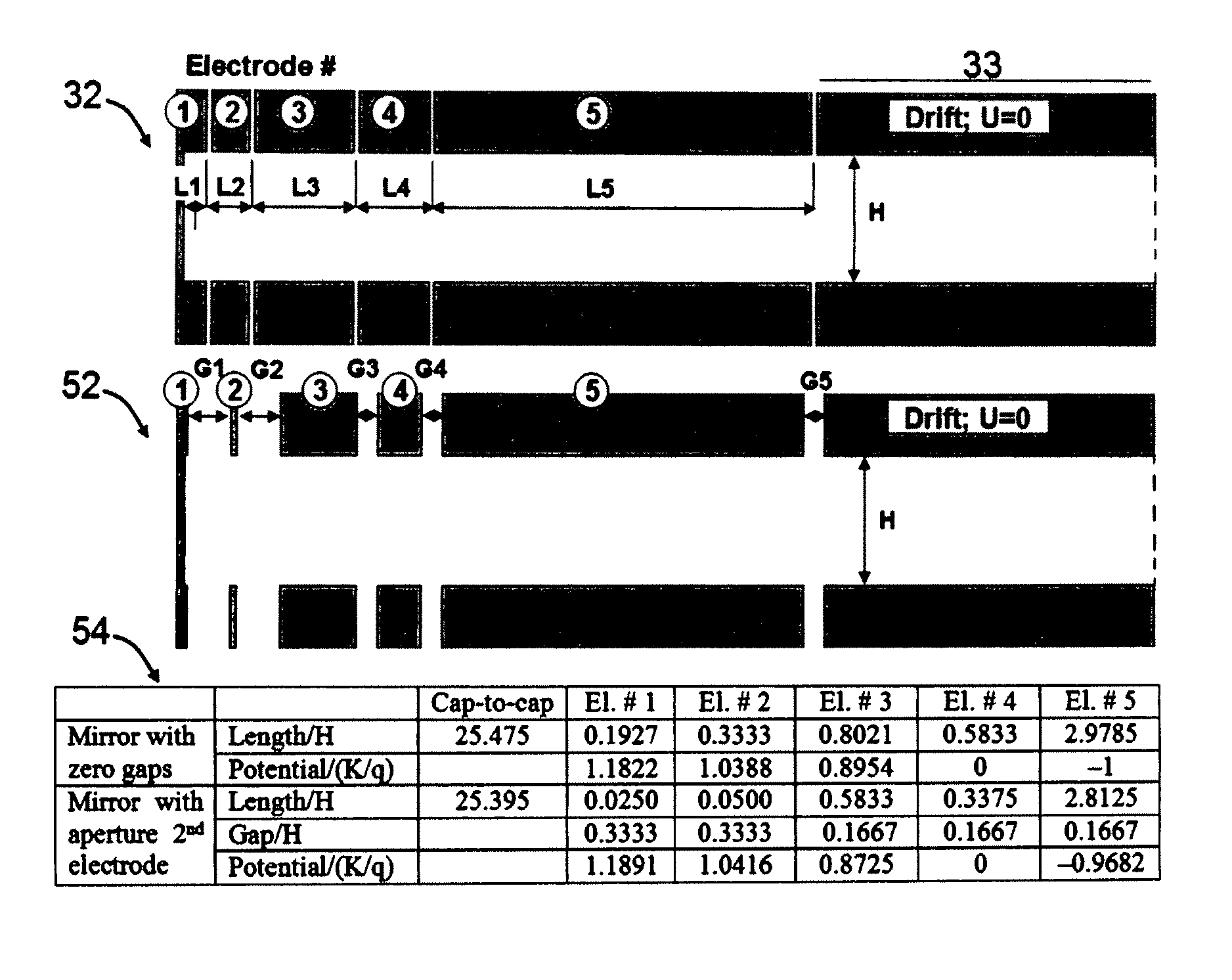
[0056]All of the considered isochronous electrostatic analyzers are characterized by two dimensional electrostatic fields in an XY-plane: X corresponds to the time separating axis (e.g. to direction of ion reflection by ion mirrors); Y corresponds to the second direction of the two-dimensional electrostatic field; Z corresponds to the orthogonal drift direction (i.e., to the direction of substantial extension of ion mirror electrodes); Y and Z are also referred as transverse directions; A corresponds to an inclination angle to the X-axis in an XZ-plane; and B corresponds to an elevation angle to the Y-axis in an XY-plane. The definition stands for both considered cases of electrostatic analyzers: the first one is composed of plates extended in the Z-direction and forms a planar two-dimensional field; the second one is composed of two sets of coaxial rings and forms a cylindrical field gap with two-dimensional field of cylindrical symmetry.

[0057]Ion packets c...


PUM


Abstract

An electrostatic ion mirror is disclosed providing fifth order time-per-energy focusing. The improved ion mirror has up to 18% energy acceptance at resolving power above 100,000. Multiple sets of ion mirror parameters (shape, length, and voltage of electrodes) are disclosed. Highly isochronous fields are formed with improved (above 10%) potential penetration from at least three electrodes into a region of ion turning. Cross-term spatial-energy time-of-flight aberrations of such mirrors are further improved by elongation of electrode with attracting potential or by adding a second electrode with an attracting potential.

Description

TECHNICAL FIELD[0001]The invention generally relates to the area of mass spectroscopic analysis, electrostatic traps and multi-reflecting time-of-flight mass spectrometers, and to an apparatus, including electrostatic ion mirrors with improved quality of isochronicity and energy tolerance.BACKGROUND[0002]Electrostatic Analyzers:[0003]Electrostatic ion mirrors may be employed in electrostatic ion traps (E-traps), open electrostatic traps (Open E-traps), and multi-reflecting time-of-flight mass spectrometers (MR-TOF MS). In all three cases, pulsed ion packets experience multiple isochronous reflections between parallel grid-free electrostatic ion mirrors spaced by a field-free region.[0004]MR-TOF:[0005]In MR-TOF, ion packets propagate through the electrostatic analyzer along a fixed flight path from an ion source to a detector, and ions' m / z ratios are calculated from flight times. SU1725289, incorporated herein by reference, introduces a scheme of a folded path MR-TOF MS, using two-d...

Claims


Application Information

Patent Timeline
Patent Type & Authority Patents(United States)
IPC IPC(8): H01J49/40H01J49/06H01J49/48H01J49/28
CPCH01J49/061H01J49/282H01J49/405H01J49/406
Inventor VERENCHIKOV, ANATOLY N.YAVOR, MIKHAIL I.POMOZOV, TIMOFEY V.
Owner LECO CORPORATION
Why Eureka
Try Eureka