Sensed motor winding current adapting blanking period between max/min values

a motor winding current and adapter technology, applied in the direction of dynamo-electric converter control, control system, electrical apparatus, etc., can solve the problem of reducing the magnitude of current, the number of steps in an electrical 360 degree revolution, and the resolution of micro-steps, so as to reduce the ripple in the current waveform, the current waveform is reduced, and the current level is higher.

Active Publication Date: 2016-07-19
TEXAS INSTR INC
View PDF29 Cites 10 Cited by
  • Summary
  • Abstract
  • Description
  • Claims
  • Application Information

AI Technical Summary

Benefits of technology

[0023]Apparatus and methods disclosed herein adapt a maximum blanking period MAX_BLANK to be proportional to a currently-selected current regulation set-point ITRIP. Doing so may decrease ripple in the motor winding current waveform, particularly at higher current steps toward the waveform peak and for higher current levels associated with higher-torque stepper motors. Ripple in the current waveform is decreased because the current regulation control logic, referred to herein as the PWM controller, is able to detect current sense feedback earlier following abrupt current changes in the motor windings. By adaptively adjusting the blanking period to a shorter time than MAX_BLANK, embodiments herein produce a winding current waveform displaying less average overshoot of the winding current past ITRIP while the PWM controller is “blind” to the sensed winding current level during blanking By reducing overshoot, disclosed embodiments and methods also reduce zero crossing distortion resulting from an “overshoot bias” that occurs when the average level of overshoot approaches small values of ITRIP close to the waveform zero crossing points as previously described.
[0025]It is noted that regulation and blanking apparatus and methods described herein for a single example winding may apply to each of multiple windings in a stepper motor. Although current waveforms may be described and illustrated in examples herein as sinusoidal, some embodiments and methods may include storing wave shape characteristics and performing operations on wave shapes other than sinusoidal wave shapes. Regulation of the winding current to ITRIP including adaptive blanking period control may alleviate variations in the winding current caused by supply voltage variations, variations in mechanical loads on the stepper motor, etc. It is also noted that example embodiments may determine whether the slope of winding current is positive or negative by sensing the polarity of a voltage drop across a sense resistor. However, any apparatus and / or methods known in the art of sensing motor winding current magnitude and performing blanking operations are contemplated by this disclosure and are equally applicable to this disclosure.
[0026]Embodiments herein more precisely regulate winding current by controlling overshoot associated with periods of fast current rise and fast current decay during a PWM cycle through adaptive adjustment of blanking time as a function of levels of winding current. More accurate current regulation may permit a greater number of finer levels of micro-stepping and consequent higher resolution. Finer micro-stepping resolution may in turn enable more precise and smoother operation of robotics including medical surgical robotic mechanisms, medical pumps, security cameras, stage lightening, cash machines etc.

Problems solved by technology

Micro-stepping resolution, the number of steps in an electrical 360 degree revolution, is limited by the accuracy with which each motor winding current level can be regulated during the constant current portion of each step.
Such overshoot may result in larger-magnitude ripple as di / dt increases for higher-magnitude motor currents and as the magnitude of the current waveform increases toward peak or decreases from peak.
This problem may impose a lower limit on the magnitude of current that may be finely regulated and thus on the driver DAC step size and resolution.
A potential problem exists with slow decay mode, particularly for smaller regulated currents.
This problem may impose a lower limit on the magnitude of current that may be finely regulated and thus on the driver DAC step size and resolution.

Method used


Image

  • Sensed motor winding current adapting blanking period between max/min values
  • Sensed motor winding current adapting blanking period between max/min values
  • Sensed motor winding current adapting blanking period between max/min values

Examples


Embodiment Construction

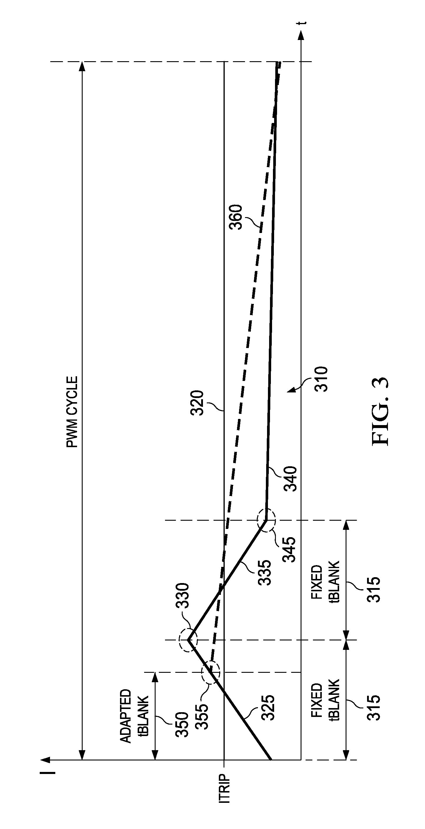
[0027]FIG. 3 is a waveform diagram 310 comparing a stepper motor winding current waveform 340 resulting from fixed blanking periods 315 to a winding current waveform 360 resulting from a winding current level adapted blanking period 350 according to various example activities and embodiments of the invention. The drive current ramp-up 325 of the fixed blanking waveform 340 overshoots the ITRIP level 320 until the end 330 of the fixed blanking period 315. The overshoot occurs because during the fixed blanking period 315 the PWM controller ignores sensed current feedback signals that would indicate the point at which the drive current ramp 325 crosses ITRIP320. Finally, at the end 330 of the fixed blanking period 315, the PWM controller acts upon the sensed current feedback signals by terminating the overshooting drive current and switching the H-bridge to fast decay mode.

[0028]The latter operation results in the fast decay portion 335 of the fixed blanking period waveform 340 during ...


PUM


Abstract

Stepper motor winding current regulation methods and apparatus adapt a maximum blanking period to generate an adapted blanking period that is proportional to a currently-selected current regulation set-point. Sensed winding current feedback is ignored at a current regulation controller during the adapted blanking period or during a minimum blanking period, whichever longer, to avoid attempting to track noise imposed upon a sensed winding current feedback signal at an initiation of rapid current changes di / dt. Doing so may decrease ripple in the motor winding current waveform and reduce zero-crossing distortion by decreasing overshoot of the current regulation set-point by the sensed winding current.

Description

PRIORITY CLAIM[0001]This application claims the benefit of priority under 35 U.S.C. §119(e) to U.S. Provisional Patent Application Ser. No. 61 / 859,610 titled “Winding Current Dependent Adaptive Blanking Time For Improved Stepper Motor Current Regulation,” filed on Jul. 29, 2013 and incorporated herein by reference in its entirety.TECHNICAL FIELD[0002]Structures and methods described herein relate to electromagnetic current regulation in rotating machinery, including current regulation in a stepper motor winding.BACKGROUND INFORMATION[0003]In stepper motors, motor position is controlled by regulating electrical current in each motor winding. Different stepper motor designs may have different numbers of windings, with the current waveform in each winding leading or lagging current waveforms associated with the other windings. For purposes of this disclosure, current regulation in a single winding is referred to as an example of the current regulation in each winding.[0004]The current ...

Claims


Application Information

Patent Timeline
Patent Type & Authority Patents(United States)
IPC IPC(8): H02P8/00H02P8/12
CPCH02P8/12
Inventor QU, WENCHAOJAIN, ANUJKEHR, RYAN PAUL
Owner TEXAS INSTR INC
Why Eureka
Try Eureka