Mobile device holder

a mobile device and holder technology, applied in the field of mobile device holders, can solve the problems of not being able to provide consumers with ready and secure access to their mobile devices, existing magnetic mounting systems that do not allow for positive positioning of devices, and not providing secure attachment to withstand movement or slippag

Active Publication Date: 2016-07-19
AIRO COLLECTIVE INC
View PDF3 Cites 76 Cited by
  • Summary
  • Abstract
  • Description
  • Claims
  • Application Information

AI Technical Summary

Benefits of technology

[0015]In a fourth preferred embodiment, the first registration member or members include a rectangular shaped registration recess, the second registration member or members include a rectangular shaped registration protrusion, and the first registration recess or recesses receives the second registration protrusion or protrusions during the coupling process. The described mounting base, as a separate component, preferably can be detachably or fixedly attached to another stationary or mobile mounting surface by means of mechanical fastener, elastomeric attachment, adhesive attachment, or integrated attachment feature. The defined flat mounting base as a separate component preferably can be fixedly secured to a flat surface via mechanical fastener, adhesives, or elastomeric attachment. The defined flat mounting base as a separate component preferably can be worn by the user by means of a harness, headband, arm band, belt clip, etc. The defined flat mounting base as a separate component preferably can be detachably secured to or integrated with a handheld pole, where the described base is pivotally attached to a fixed or extendable pole. The defined flat mounting base as a separate component preferably can be detachably secured to or integrated with a threaded tri-pod mount. The defined flat mounting base as a separate component preferably can be fixedly Integrated into a wallet, by various means of attachment.
[0016]These and other features and advantages of the invention will become more apparent with a description of preferred embodiments in reference to the associated drawings.

Problems solved by technology

However, conventional mobile device holders may not provide consumers with ready and secure access to their mobile devices.
More specifically, existing magnetic mounting systems do not allow for positive location of the device to the mount.
They also do not provide for secure attachment to withstand movement or slipping due to vibratory forces or due to more extreme sporting activities.

Method used


Image

  • Mobile device holder
  • Mobile device holder
  • Mobile device holder

Examples


Embodiment Construction

[0058]The following preferred embodiments are directed to mobile device holders for affixing mobile devices to other objects. Mobile devices provide users with real-time access to telephony, Internet, text messaging, GPS navigation, audio, and video, for example. Many activities require a convenient means for attaching and detaching mobile devices to and from other objects.

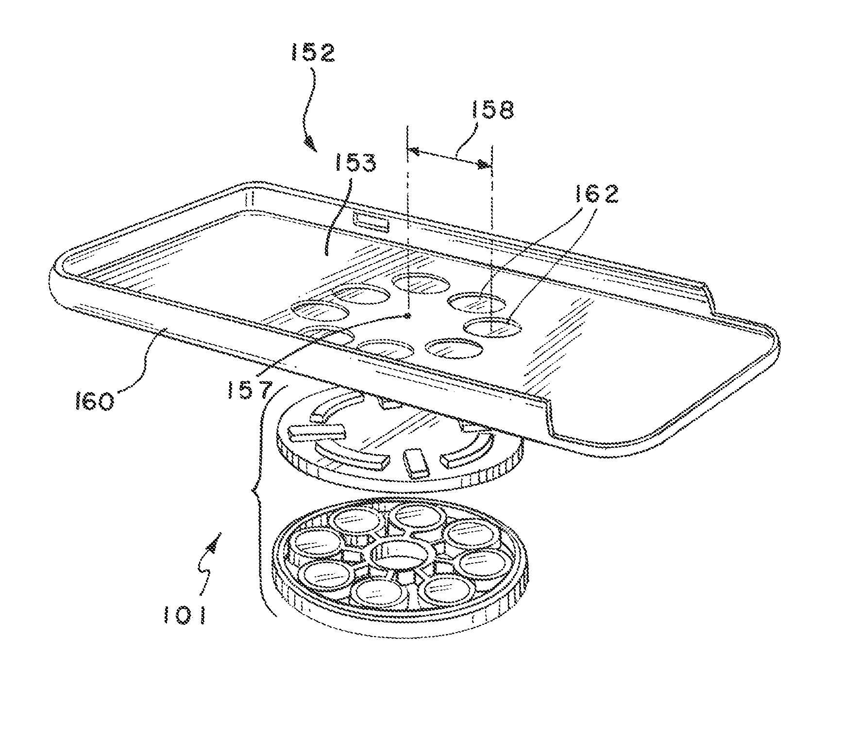
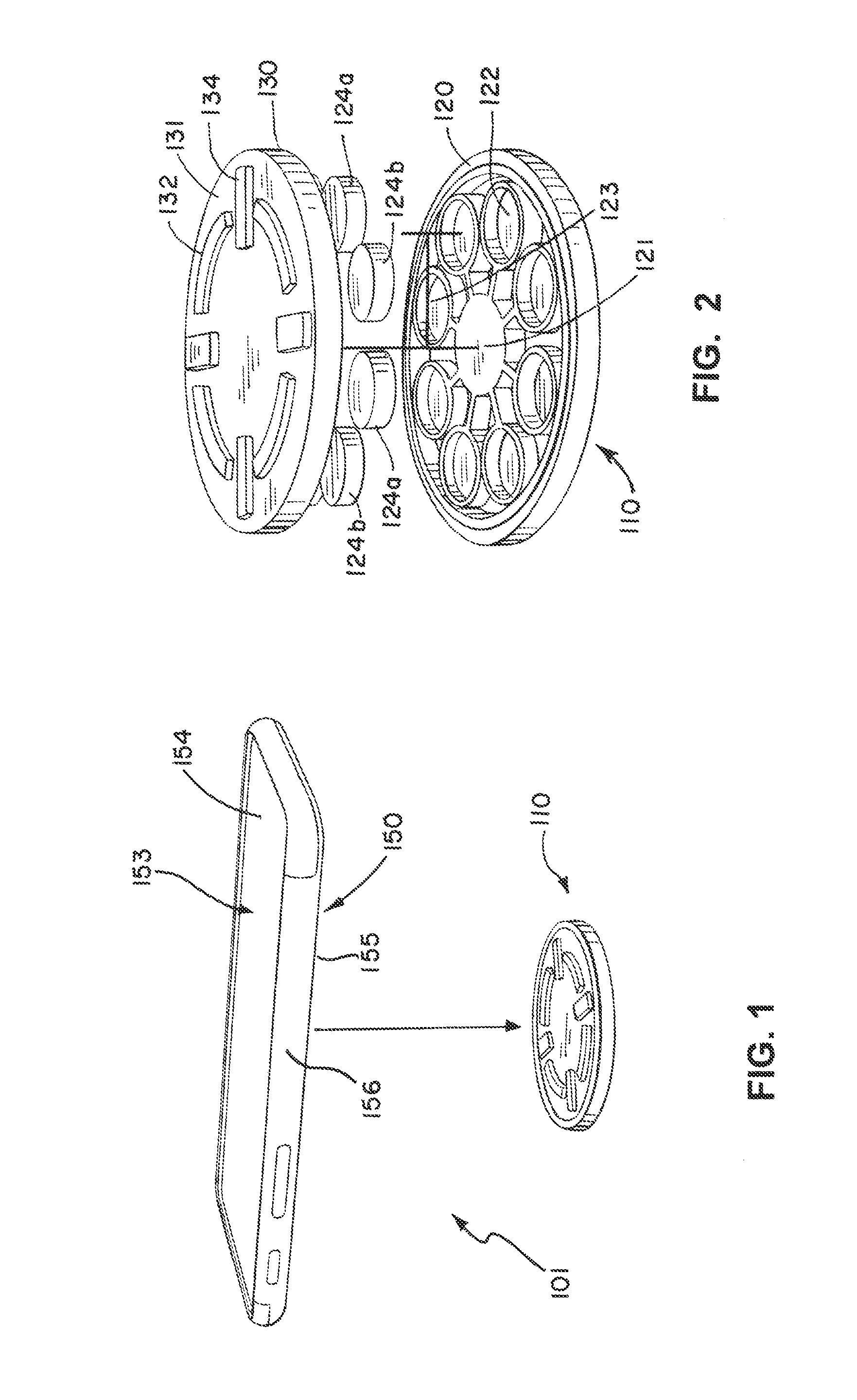
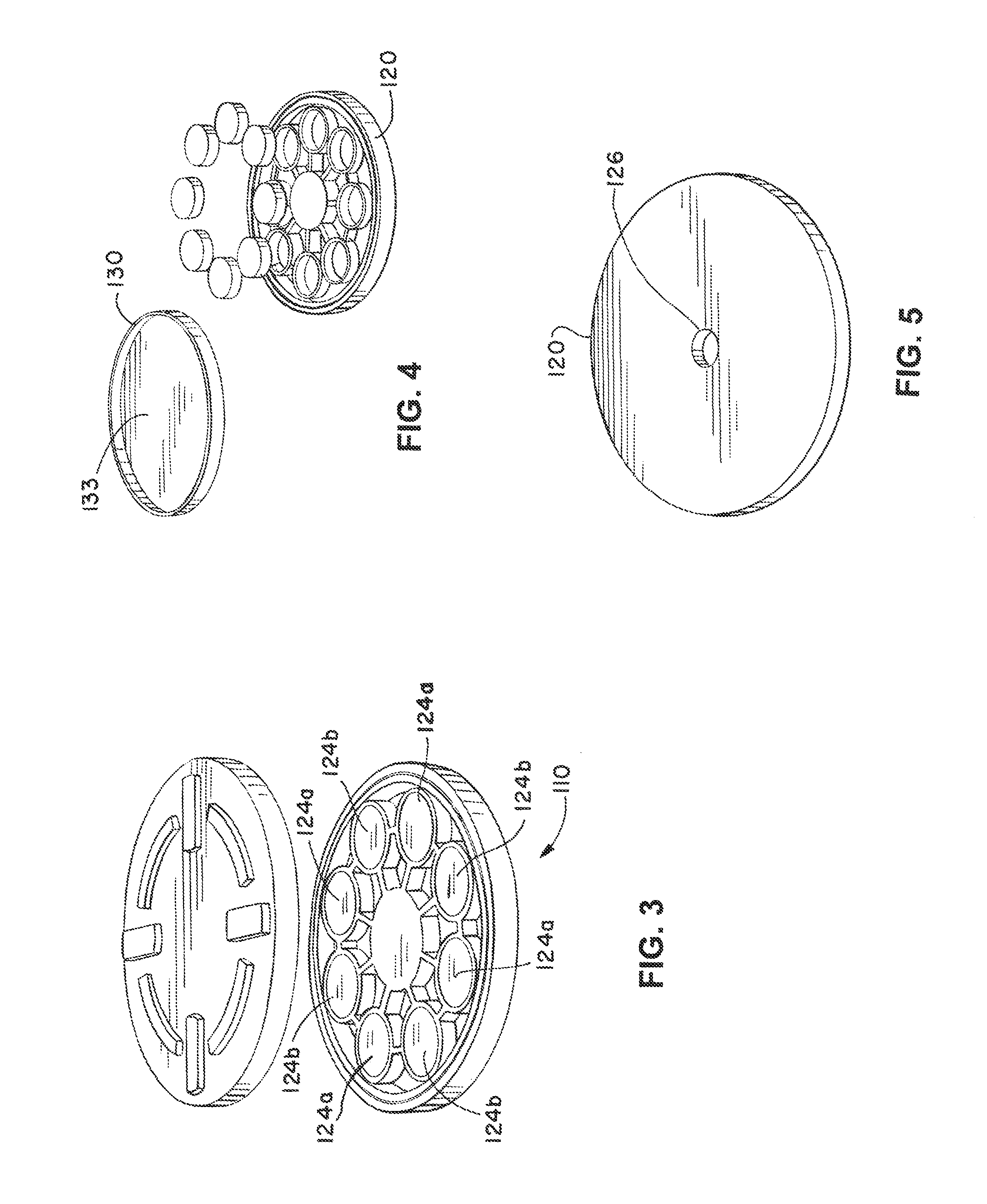
[0059]In one or more embodiments, a two-piece mobile device holder having a case assembly and a mounting assembly is contemplated. The case assembly is configured to receive and secure a mobile device, such as a smart phone. The mounting assembly is configured to be detachably coupled to other objects, such as to mounts to automobile visors or automobile air conditioning vents. A first set of permanent magnets is arranged in a circular pattern in the case assembly; and a second set of permanent magnets is arranged in a circular pattern in the mounting assembly. In one or more embodiments, the magnets in both the f...


PUM


Abstract

A two-piece mobile device holder having a case assembly and a mounting assembly is disclosed. The case assembly is configured to receive and secure a mobile device such as a smart phone. The mounting assembly is configured to be detachably coupled to other objects. Sets of permanent magnets are arranged in a circular pattern in the case assembly and the mounting assembly. The magnets in both the first and second set of magnets are arranged with alternating magnetic polarity. As the case assembly is placed on top of the mounting assembly, the magnets in the mounting assembly will attract magnets with opposite polarities in the case assembly. A user may detach the case assembly from the mounting assembly by rotating the case assembly such that the magnets in the case assembly are now adjacent to magnets in the mounting assembly of the same polarity.

Description

BACKGROUND OF THE INVENTION[0001]1. Field of the Invention[0002]The present invention relates in general to mobile device holders for mobile electronic devices. More particularly, the invention is directed to mobile device holders employing magnets as the coupling mechanism.[0003]2. Description of the Related Art[0004]Many consumers rely on mobile electronic devices for telephony, Internet access, audio, video, navigation, and entertainment. While the devices are readily carried in pockets or purses, there are many activities in which consumers prefer to mount the mobile electronic devices to other objects. However, conventional mobile device holders may not provide consumers with ready and secure access to their mobile devices. More specifically, existing magnetic mounting systems do not allow for positive location of the device to the mount. They also do not provide for secure attachment to withstand movement or slipping due to vibratory forces or due to more extreme sporting acti...

Claims


Application Information

Patent Timeline
Patent Type & Authority Patents(United States)
IPC IPC(8): H04M1/02H04B1/3877F16B1/00F16M13/02F16M11/22F16M11/24B60R11/02A45F5/00A45F5/02A45F5/10B60R11/00
CPCH04B1/3877F16B1/00F16M13/02F16M11/22F16M11/24B60R11/02A45F5/00A45F5/021A45F5/10F16M11/242B60R2011/0008B60R2011/0035A45F2005/008A45F2005/1006F16B2001/0035B60R2011/007A45F2200/0516H04B1/3888F16M11/041F16M11/08F16M11/2021F16M13/022F16M13/04H02G3/10H02G3/14H02G3/305F16B2200/83
Inventor SCHMIDT, STEVE
Owner AIRO COLLECTIVE INC
Why Eureka
Try Eureka