
Luminaire for road illumination with sensor

a technology of road illumination and sensor, which is applied in the direction of electroluminescent light sources, sustainable buildings, energy-efficient lighting, etc., can solve the problems of inability to disclose a clear technical teaching, and achieve the effect of improving possibilities, improving the picture of road luminance, and maintaining constant road luminan

Active Publication Date: 2016-07-19
SIGNIFY HLDG BV
View PDF14 Cites 0 Cited by
  • Summary
  • Abstract
  • Description
  • Claims
  • Application Information

AI Technical Summary

Benefits of technology

[0014]Said provided information thus can be used to adjust the light output of the light source / luminaire, so that the luminance of the road can be maintained rather constant under different weather and / or road conditions. Keeping the luminance constant appears to improve the safety of road users, who are not faced with strongly variable light intensities on the road. This applies especially to drivers of cars, trucks and other motorized vehicles, who are especially sensitive to variations in the road luminance.
[0018]Another interesting embodiment of the invented luminaire shows the special characteristic that the sensor unit works with an emitter element. The presence of an emitter element which works together with the sensor element in the sensor unit may improve the accuracy of the measured specular and diffuse reflection components of the total reflection. This may lead to optimization in the adjustment of the light output of a luminaire or even of a luminaire system which includes a luminaire according of the present embodiment. With the help of an emitter element, the total reflection of the surface of the road as well as its two components (specular and diffuse reflection) can be measured with more accuracy due to an improved signal-to-noise-ratio. Such emitter element is preferably a laser-emitter. The emitter may be incorporated in the sensor unit or in another element of the luminaire.
[0021]Also interesting is the embodiment of the luminaire having the feature that the housing contains at least two light sources with related optics, which light sources can be powered individually during the operation of the luminaire. A luminaire according to this design has the advantage that the intensity of the light output as well as the beam shape emitted from the luminaire can be changed independently and continuously.
[0022]Much interest is also devoted to the embodiment of the invented luminaire which has the feature that wherein each of the light sources comprise at least one LED. The use of LEDs in outdoor luminaires provides different advantages. First, the maintenance costs of the luminaires are rather low due to relatively low energy consumption of the LEDs and their extreme long lifetime. Moreover, the light intensity of LEDs can be adapted rather simply as compared with other types of light sources, like sodium-vapor lamps or fluorescent lamps. The intensity of the light output of LEDs can be adapted by changing the overall current flow through the LEDs or using simple pulse width modulation scheme's which are widely available to persons skilled in this technical area.
[0024]A further embodiment of the luminaire according to the invention has the feature that the luminaire further comprises a second sensor adapted for measuring atmospheric precipitation. With such additional sensor, the amount of the rain, fog or hail density can be measured during periods in which such atmospheric precipitation occurs. The measured values can be used together with the measured values of the reflected light obtained with the sensor unit to determine a better picture of the luminance of the road. So, this combined info may improve the possibilities to maintain said luminance of the road constant.
[0025]A very interesting embodiment of the invented luminaire has the feature that the luminaire further comprises a communication unit for communication data with other luminaires. Thus, data measured by means of the sensor unit present in this luminaire may be shared with other luminaires which are positioned at a relatively short distance from the luminaire of this design. The light output of the other luminaires may therefore be controlled by means of the data measured by the luminaire having the communication unit. The other luminaire may therefore lack a sensor unit and a calculation unit. When all luminaires have sensors, the communication between the luminaries decreases the possibility of errors and thus makes the system more robust.

Problems solved by technology

The mentioned patent publication however has the clear problem in that it fails in disclosing a clear technical teaching how various weather types and / or road conditions can be distinguished by the sensor.

Method used


Image

  • Luminaire for road illumination with sensor
  • Luminaire for road illumination with sensor
  • Luminaire for road illumination with sensor

Examples


Embodiment Construction

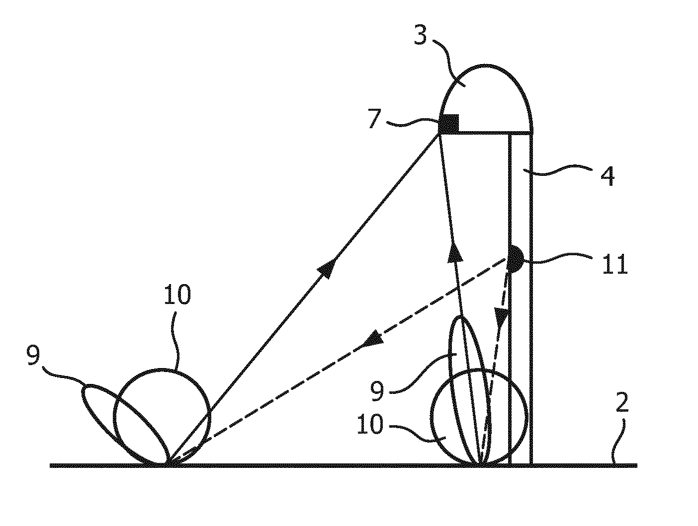
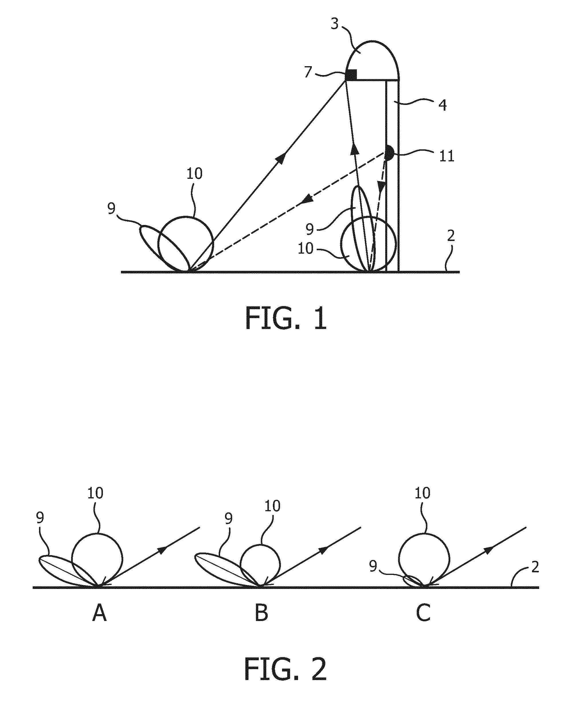
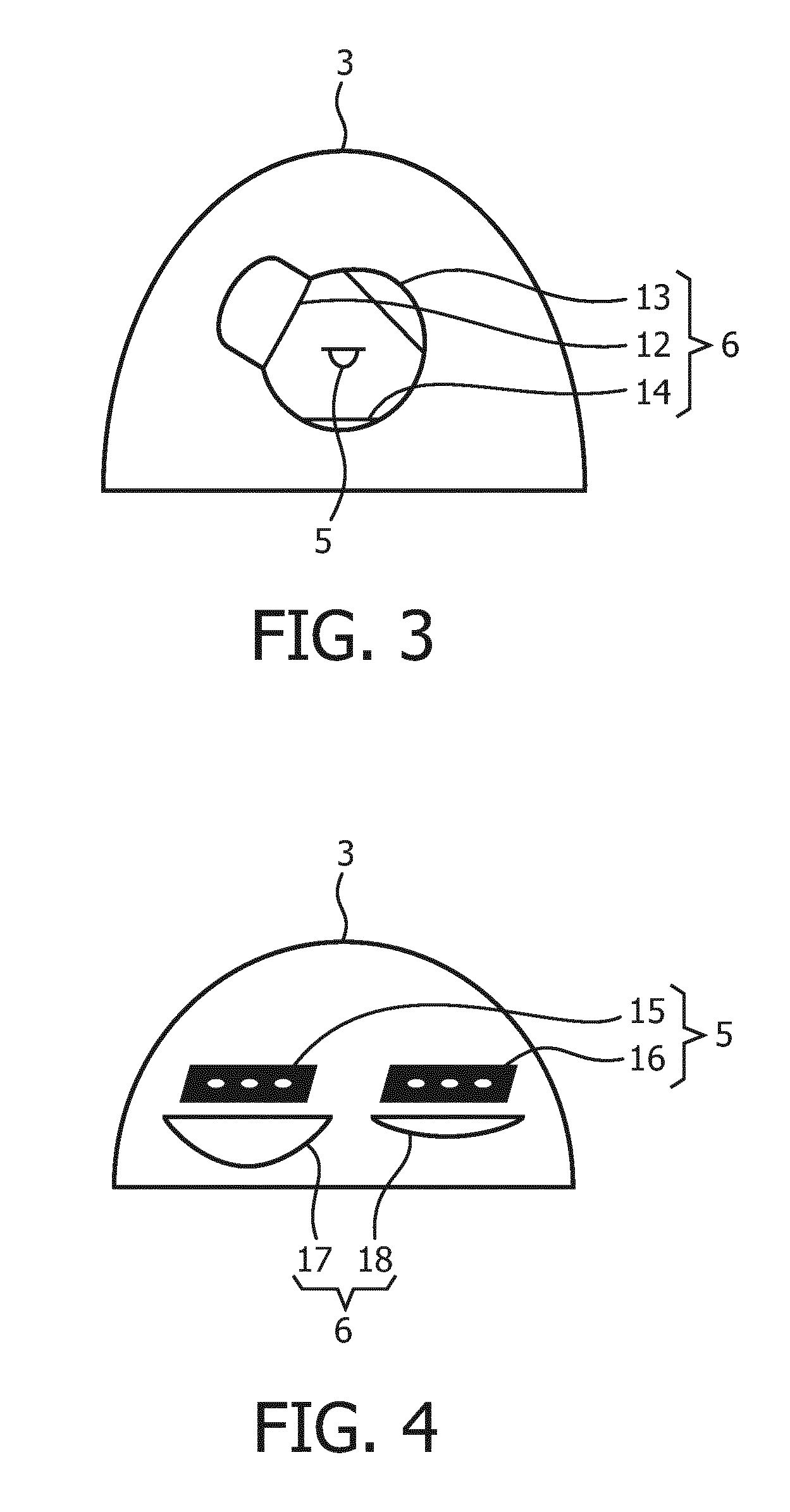
[0035]FIG. 1 schematically shows a luminaire 1 according to the present invention, for illumination of a road 2. Luminaire 1 comprises a housing 3 which is connected to a pole 4. Housing 3 contains a light source 5 (not shown) formed as a plurality of LEDs, which are provided with optics 6 (not shown). Details of light source 5 and optics 6 are depicted in FIGS. 3 and 4.

[0036]Luminaire 1 further comprises a sensor unit 7, which is adapted to measure optical properties of the surrounding of the luminaire and a calculation unit 8 (not shown) adapted to calculate parameters for controlling the light output of the luminaire based on the optical properties measured by the sensor unit 7. Under the present weather and / or road conditions, reflections from road 2 are measured. Sensor unit 7 is adapted to measure specular reflection 9 and diffuse reflection 10 of the surrounding of the luminaire 1 under at least two different angles, one of them substantially being the angle of the specular r...


PUM


Abstract

The invention relates to a luminaire for road illumination, said luminaire (1) comprising a housing (3) containing a light source (5) provided with optics (6). The luminaire further comprising a sensor unit (7) adapted to measure optical properties of the surrounding of the luminaire and a calculation unit adapted to calculate the parameters for controlling the light output of the luminaire based on the optical properties measured by the sensor unit. According to the invention, the sensor unit is adapted to measure specular and diffuse reflection properties of the surrounding of the luminaire. These optical properties allow determining the type of weather or the road condition and adjustment of the light output of the luminaire, thus improving the road safety.

Description

CROSS-REFERENCE TO PRIOR APPLICATIONS[0001]This application is the U.S. National Phase application under 35 U.S.C. §371 of International Application No. PCT / EP2014 / 058002, filed on Apr. 18, 2014, which claims the benefit of European Patent Application No. 13166745.3, filed on May 7, 2013. These applications are hereby incorporated by reference herein.FIELD OF THE INVENTION[0002]The invention relates to a luminaire for road illumination, said luminaire comprising a housing containing a light source provided with optics, the luminaire further comprising a sensor unit adapted to measure optical properties of the surrounding of the luminaire and a calculation unit adapted to calculate the parameters for controlling the light output of the luminaire based on the optical properties measured by the sensor unit. The invention also relates to a system of luminaires for road illumination, each luminaire comprising a housing containing a light source with related optics and a communication uni...

Claims


Application Information

Patent Timeline
Patent Type & Authority Patents(United States)
IPC IPC(8): H05B33/08H05B37/02H05B44/00
CPCH05B37/0218H05B33/0854Y02B20/46Y02B20/72H05B47/11Y02B20/40H05B47/10H05B45/12
Inventor SEPKHANOV, RUSLAN AKHMEDOVICHPIJLMAN, FETZEDE ZWART, SIEBE TJERK
Owner SIGNIFY HLDG BV
Learn More