Apparatus for depositing

a technology for food products and apparatuses, which is applied in the direction of dough shaping, manufacturing tools, packaging goods types, etc., can solve the problems of difficult to accurately control the flow of food products through the outlet orifice, complicated structure and high production and commissioning costs, and achieve the effect of improving the accessibility for repair or replacement and positive operation of the apparatus

Active Publication Date: 2016-07-26
SOC DES PROD NESTLE SA
View PDF38 Cites 1 Cited by
  • Summary
  • Abstract
  • Description
  • Claims
  • Application Information

AI Technical Summary

Benefits of technology

[0011]The invention thus provides a depositor which is capable of positive operation in the sense that the outlet orifice can be opened and closed to accurately control the flow of the food product. Furthermore, the essential features of the invention described above allow for reduced structural complexity as compared to known depositors, such as piston-type depositors. As a consequence, the apparatus may be manoeuvred at a high speed to deposit the food product in a desired arrangement.
[0035]The controller may be arranged to move the apparatus over the support such that the formation of “tails” is avoided when an outlet orifice is closed. For example, tailing can be avoided by a reverse motion of the apparatus at the end of a deposit stroke. Tailing may also be controlled by providing an arrangement whereby the apparatus can be moved upwards (away from) and / or downwards (towards) the support at the end of a deposit stroke.

Problems solved by technology

A problem associated with piston-type depositors is that arrays of such depositors, which may be required for the rapid and even filling of mould cavities or the rapid deposition of a continuous layer of the food product, are structurally complicated and expensive to produce and commission.
A further problem associated with piston-type depositors is that it can be difficult to accurately control the flow of the food product through the outlet orifice, particularly when the food product is a liquid having a low viscosity.

Method used


Image

  • Apparatus for depositing
  • Apparatus for depositing

Examples


Embodiment Construction

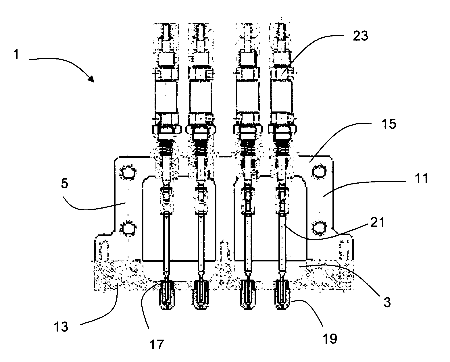
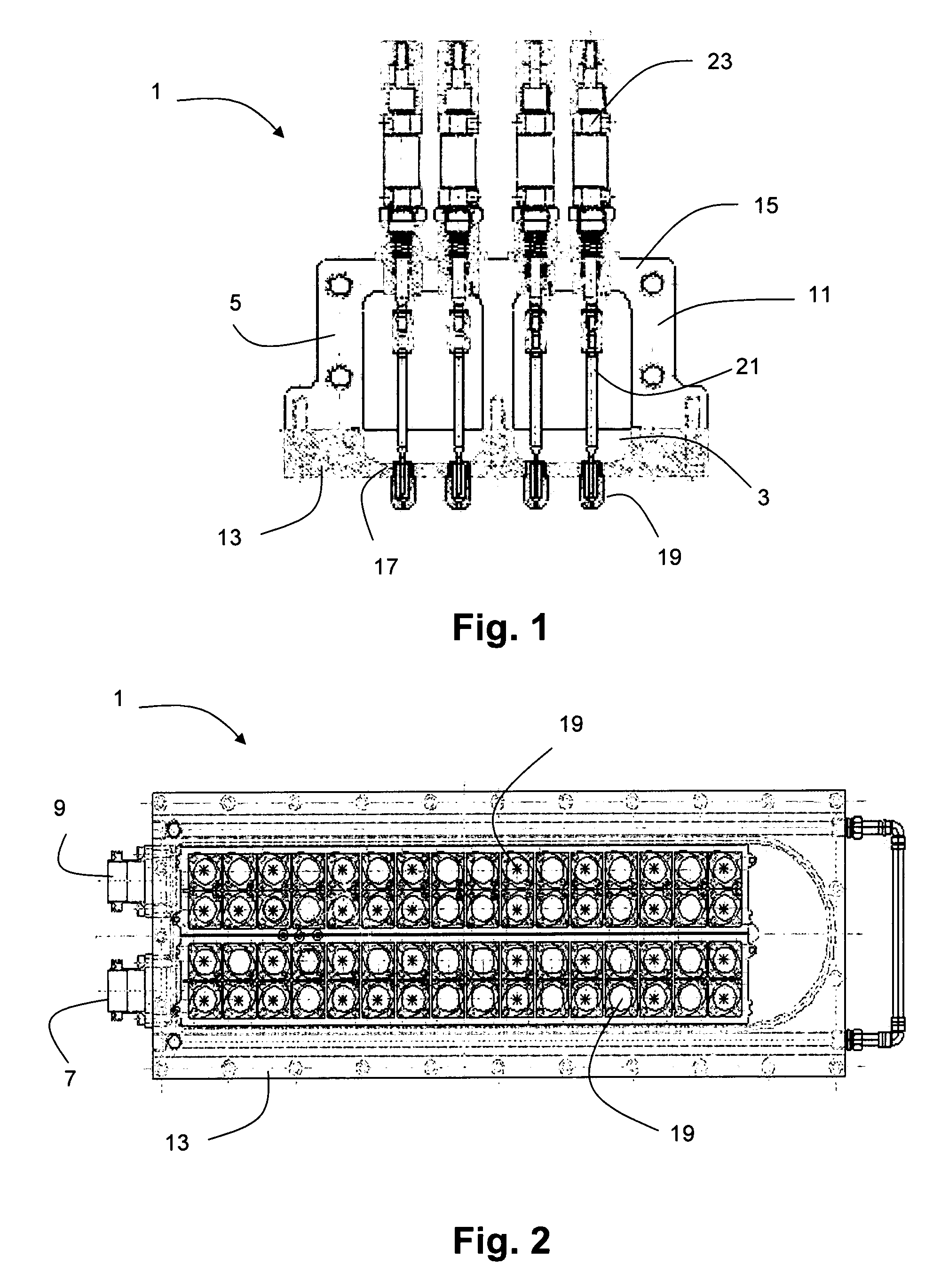
[0045]The invention provides an apparatus for depositing a liquid, semi-liquid or semi-solid food product. The apparatus comprises a fixed volume chamber for receiving the food product under a positive pressure, the chamber being defined by chamber walls, one of the chamber walls being provided with an outlet orifice for depositing the food product, the outlet orifice being provided with a first sealing surface. The apparatus also comprises a valve spindle arranged for reciprocating movement within the chamber, the length direction of the valve spindle extending substantially perpendicular to the chamber wall in which the outlet orifice is provided, a first end of the valve spindle being provided with a second sealing surface. The second sealing surface of the valve spindle is arranged for abutting the first sealing surface of the outlet orifice to thereby close the outlet orifice.

[0046]With reference to FIGS. 1 and 2, an apparatus 1 for depositing a liquid, semi-liquid or semi-soli...


PUM

PropertyMeasurementUnit
frequencyaaaaaaaaaa
pressureaaaaaaaaaa
frequencyaaaaaaaaaa

Abstract

An apparatus for depositing a liquid, semi-liquid or semi-solid food product. The apparatus comprises a fixed volume chamber for receiving the food product under a positive pressure, the chamber being defined by chamber walls, one of the chamber walls being provided with an outlet orifice for depositing the food product, the outlet orifice being provided with a first sealing surface. The apparatus also comprises a valve spindle arranged for reciprocating movement within the chamber, the length direction of the valve spindle extending substantially perpendicular to the chamber wall in which the outlet orifice is provided, a first end of the valve spindle being provided with a second sealing surface. The second sealing surface of the valve spindle is arranged for abutting the first sealing surface of the outlet orifice to thereby close the outlet orifice.

Description

FIELD OF THE INVENTION[0001]This invention relates to an apparatus for depositing a liquid, semi-liquid or semi-solid food product. More particularly, but not exclusively, the invention relates to such an apparatus for use in filling mould cavities for finished confectionery products.[0002]The invention also relates to a method for depositing a liquid, semi-liquid or semi-solid food product.BACKGROUND TO THE INVENTION[0003]It is known to deposit liquid, semi-liquid or semi-solid food products in confectionery manufacturing processes. Such products may, for example, be deposited into a mould cavity for producing a finished confectionery product. One example of such a process is the depositing of liquid chocolate into a mould cavity for the production of a chocolate bar. Fillings for confectionery products, such as fondants, caramels, mousses or truffles, may also be deposited.[0004]In known confectionery manufacturing processes, liquid, semi-liquid or semi-solid food products are dep...

Claims


Application Information

Patent Timeline
Patent Type & Authority Patents(United States)
IPC IPC(8): A23G3/02F16K1/08A23G1/00B05C5/02A23G3/34A21C5/00A23G3/20A21C11/16A23G1/20A21C9/08F16K1/04
CPCF16K1/08A23G1/0066A23G1/206A23G3/0027A23G3/0257A23G3/203B05C5/0225A21C5/006A21C9/08A21C11/16A23G1/205A23G3/0236A23G3/0252A23G3/20A23G3/2023F16K1/04
Inventor WALKER, JOHN HOWARDLEADBEATER, JOHN MICHAELSUTTON, JONATHAN
Owner SOC DES PROD NESTLE SA
Why Eureka
Try Eureka