Piezoelectric valve and pump actuator

a technology of pump actuator and valve body, which is applied in the direction of valve details, valve operating means/release devices, mechanical equipment, etc., can solve the problems of difficult accurate control of movement and positioning of the armature valve member, and affecting the operation of the solenoid coil. , to achieve the effect of ensuring the dissipation of hea

Inactive Publication Date: 2013-10-24
FOUNDER
View PDF4 Cites 9 Cited by
  • Summary
  • Abstract
  • Description
  • Claims
  • Application Information

AI Technical Summary

Benefits of technology

[0031]Optionally and most preferably the piezoelectric control module according to the present invention provides a valve gating module that provides a control module that...

Problems solved by technology

However to achieve linear flow control is often difficult to accurately control movement and positioning of the armature valve member through the control voltage or electrical current applied to the solenoids.
Magnetic field that produced by the solenoid coil is susceptible to variability in their operation due to inductive delays, eddy currents, hysteresis, heat, magnetic saturation, air gap between the solenoid and the armature.
Solenoid base valves are susceptible to the basic construction of the valves which required spring preloads characterized by the varying fluid flow forces.
Other solenoids drawbacks are: current must be continuously supplied to the solenoid in order to maintain the solenoid active, large current has to be provided to switch the solenoid while lower current is required to hold the solenoid in the define.
Thus it is requiring a high current power source leads to heating of the solenoid which might be hazardous ...

Method used


Image

  • Piezoelectric valve and pump actuator
  • Piezoelectric valve and pump actuator
  • Piezoelectric valve and pump actuator

Examples


Embodiment Construction

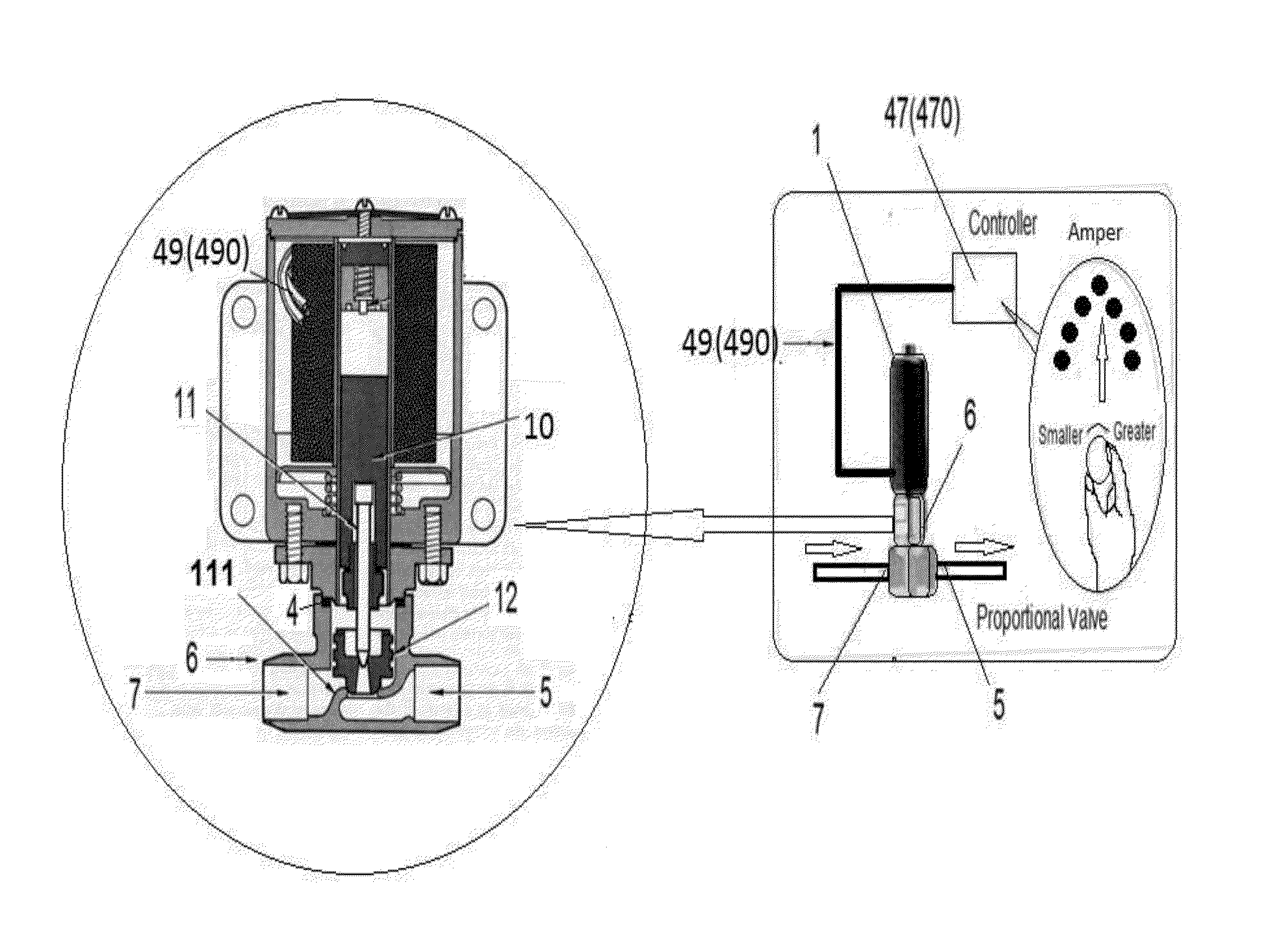
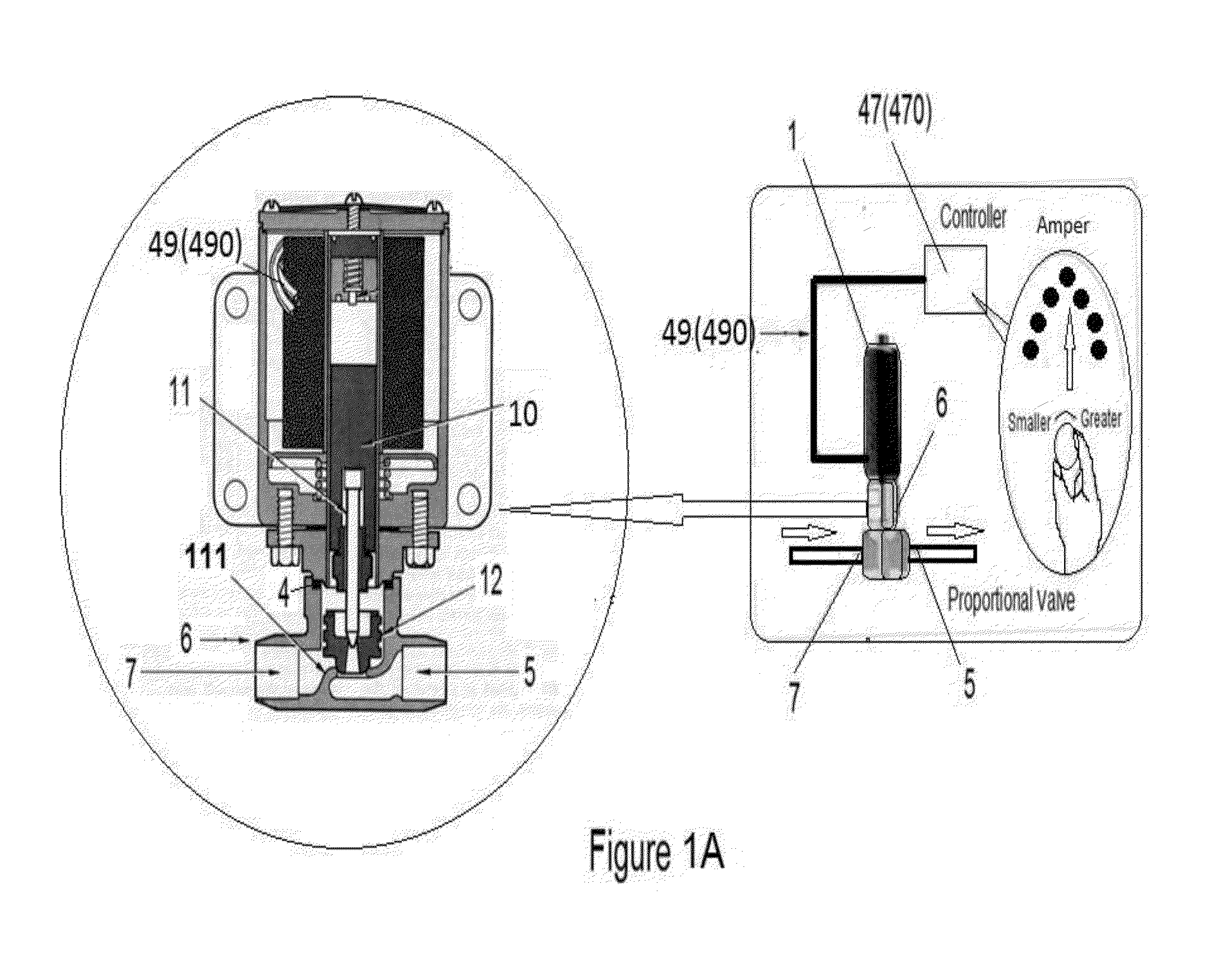
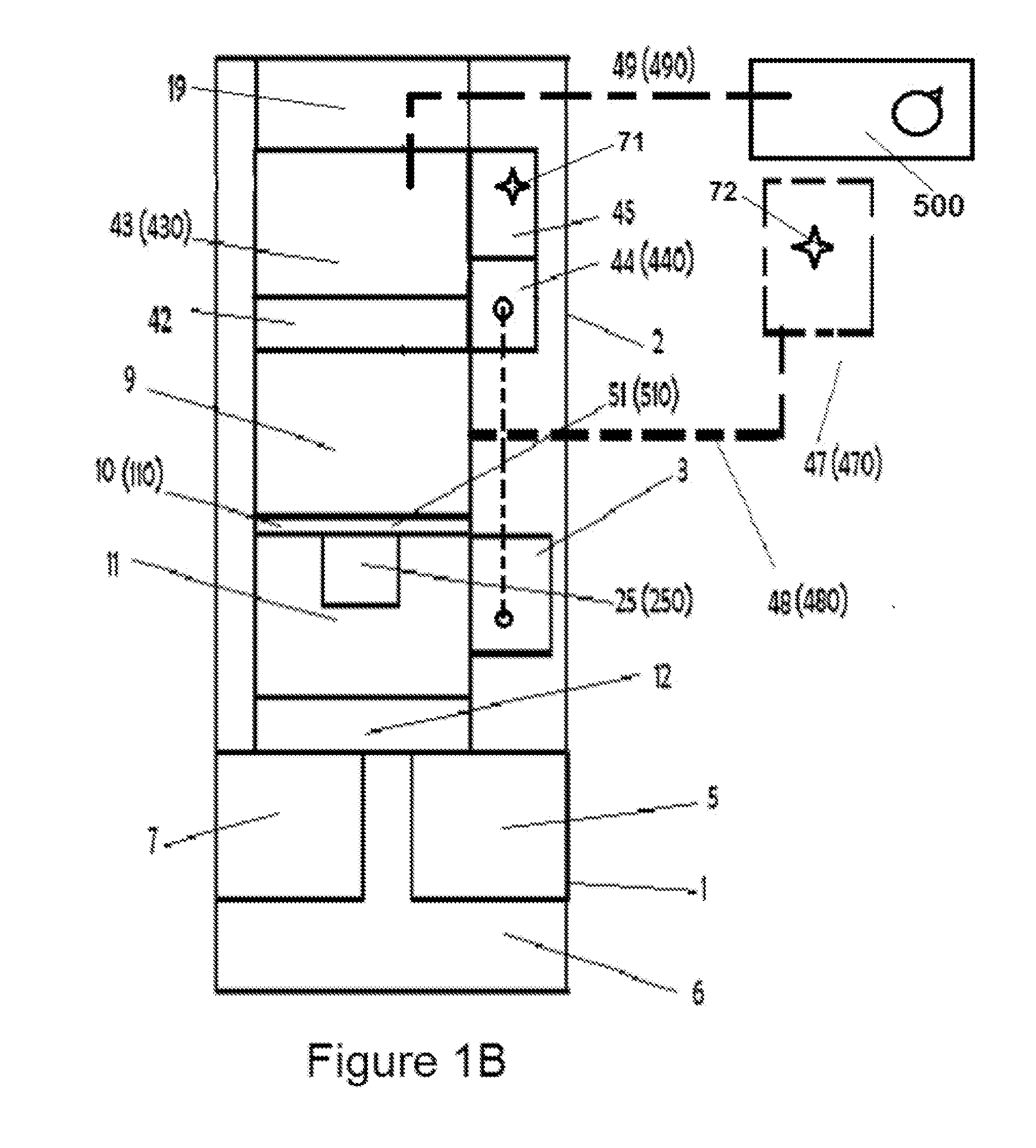
[0059]The principles and operation of the present invention may be better understood with reference to the drawings and the accompanying description. The following figure references labels are used throughout the description to refer to similarly functioning components are used throughout the specification herein below:[0060]1 Valve—of the shelf, modified or new type;[0061]2 Valve housing;[0062]3 Optional encoder unit;[0063]4 Valve seal gasket;[0064]5 Valve outlet fitting connection;[0065]6 Valve body;[0066]7 Valve inlet fitting connection;[0067]9 Valve piezoelectric actuator;[0068]10 Valve piezoelectric actuators stem;[0069]110 Swivel piezoelectric actuator rotational axis shaft;[0070]11 Valve armature and diaphragm seat;[0071]111 Valve seat;[0072]12 Valve diaphragm;[0073]13 Piezoelectric actuator seat plate;[0074]14 Piezoelectric actuator moving ring member;[0075]15 Piezoelectric actuator pivot seat;[0076]16 Piezoelectric actuators housing;[0077]17 Piezoelectric actuator crystal;[...


PUM


Abstract

The proposed valves and/or fluid pumps are controlled with a piezoelectric actuator, which provides very low power consumption, low cost, very compact designs, high speed response, long life, hysteresis free and linear operation, long displacement over 50 mm and high torque over 400 Newton. A steady continuous flow of a media is achieved by supplying a power profile to the actuator via an electronic circuitry connected to electrodes attached to the piezoelectric actuator.

Description

REFERENCE TO PREVIOUS APPLICATIONS[0001]This application claims priority to U.S. provisional patent application No. 61 / 687,322 filed May 15, 2011 entitled “PIEZOELECTRIC VALVE AND PUMP ACTUATOR”.FIELD OF THE INVENTION[0002]The present invention relates to valves and / or fluid pumps controlled with a piezoelectric actuator and providing a replacement or retrofit to valve solenoid control unit.BACKGROUND OF THE INVENTION[0003]Most valves and pumps actuated by electromagnetic and solenoid actuator. Some valves are controlled by piezoelectric actuator with limited force and / or stroke in order to control the flow of fluid through the valve system.[0004]Flow control of a flowing fluid through a valve is generally achieved by changing the size of the orifice in the flow line. The change of the orifice size is generally involves moving of an armature up and clown relative to its corresponding valve seat.[0005]The basic operation of proportional solenoid valve: The armature is attracted to th...

Claims


Application Information

Patent Timeline
IPC IPC(8): F16K31/02
CPCF16K31/004F04B17/003F04B19/006F04B43/046Y10T137/7758
Inventor KRITZMAN, AMNON
Owner FOUNDER
Why Eureka
Try Eureka