Heat dissipative air guide

a technology of air guide and heat dissipation air, which is applied in the direction of ventilation panels with screening provisions, cooling/ventilation/heating modifications, and screening casings. it can solve the problems of poor airflow conditions, insufficient airflow, and crowded placement of electronic modules on the motherboard of the device, so as to increase the rate of thermal transfer

Active Publication Date: 2016-07-26
MOLEX INC
View PDF22 Cites 13 Cited by
  • Summary
  • Abstract
  • Description
  • Claims
  • Application Information

AI Technical Summary

Benefits of technology

[0008]In a third embodiment, the thermal transfer member is a large member that integrates two transfer members disposed in opposition to a respective pair of electronic modules into a single element. The air guide portion of the shielding cage assembly is also formed as part of the large member. This large member may have one or two bottom surfaces that define contact surfaces which extend into the interior of the shielding cage into contact with the top surface of the module. A thermal interposer sheet may be applied to the contact surface(s) to increase the rate of thermal transfer. Alternatively, the bottom surfaces of the thermal transfer members may be spaced apart from the module top surfaces to provide an air flow channel across the module, the exit of which is defined by the vertical passages in the thermal transfer members. In the instance where the thermal transfer members contact the modules, the bottom surface contains one or more recesses that open to the space between the top surface of the module and the top wall of the shielding cage assembly. Air passage extension members may be provided in the form of pipes that fit into the passages formed in the thermal transfer members.

Problems solved by technology

These fins transfer heat in a static manner by conduction from the module to the air passing across or beside them, and do not promote air flow from the interior of the shielding cage.
Often the location of the electronic modules on the device motherboard is very crowded and does not provide optimal airflow along the heat sink fins.
The increasing densities of the boards necessitate a crowded periphery, where the number of elements near the cages create even poorer airflow conditions.

Method used


Image

  • Heat dissipative air guide
  • Heat dissipative air guide
  • Heat dissipative air guide

Examples


second embodiment

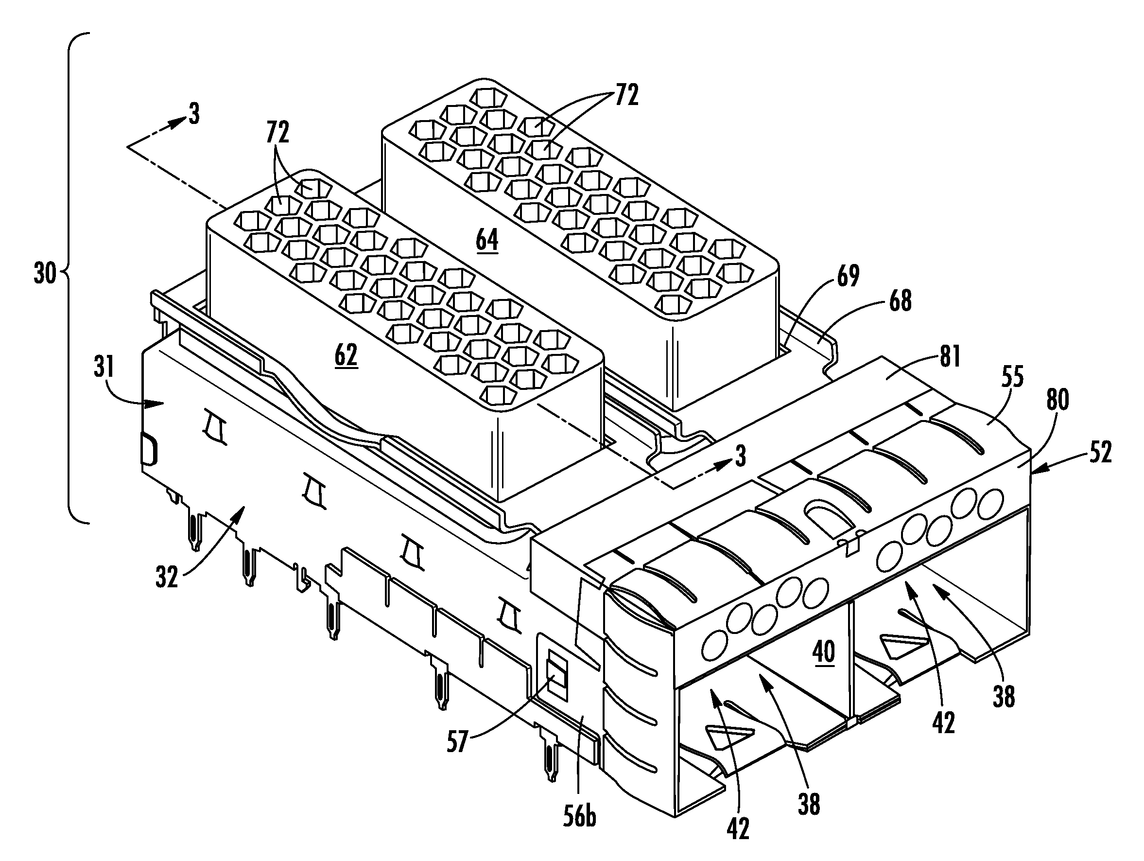
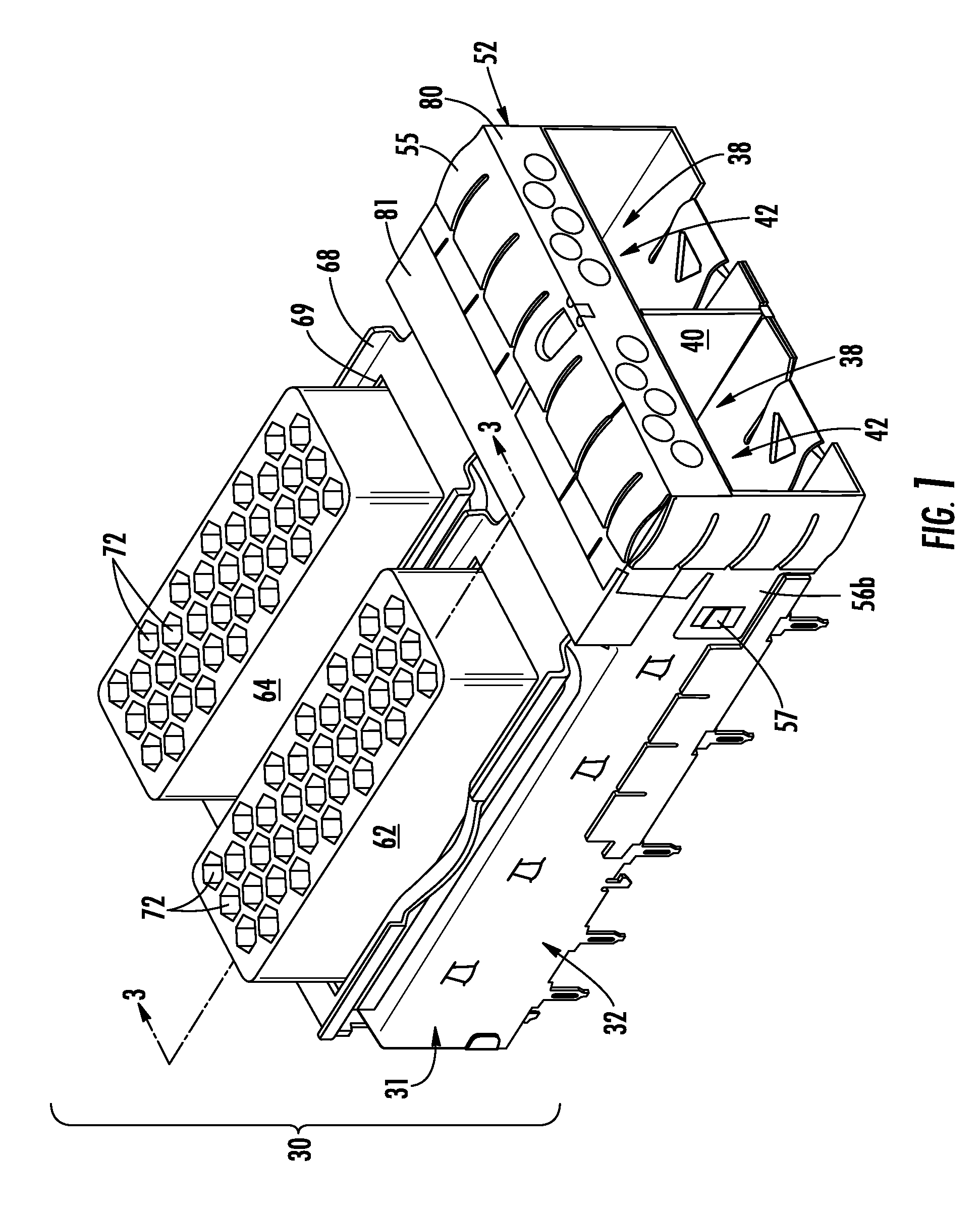
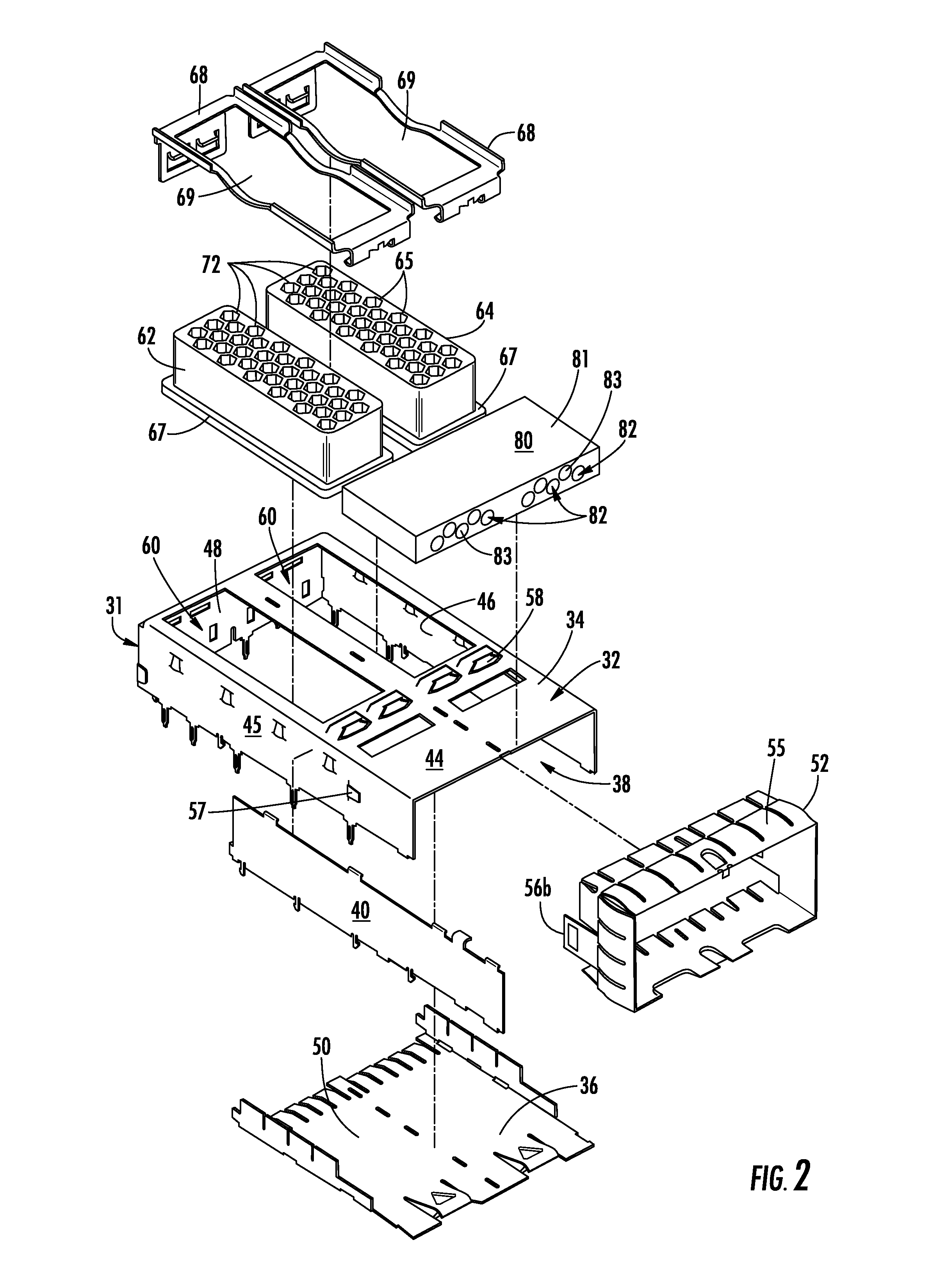
[0050]FIGS. 6-8 illustrate a heat dissipative air guide constructed in accordance with the principles of the Present Disclosure. A shielding cage assembly 100 is shown with two module-receiving bays 102. The shielding cage body 104 has first and second openings 105, 106 disposed on a top wall 108 of the cage body 104. The first openings 105 communicate with the bottoms of the two thermal transfer members 110, 112. One of the thermal transfer members 110 of this embodiment extends partially into the interior of its respective module-receiving bay 102. Second openings 106 of the cage body 104 are disposed underneath and adjacent to an air guide 114 that extends transversely with respect to the module-receiving bays 102 and of the two thermal transfer members 110, 112. The thermal transfer members 110, 112 of this embodiment each have a lower base portion 116 which contains a plurality of air exit passages 72 and each thermal transfer member 110, 112 further includes upper portions 117...

third embodiment

[0053]FIGS. 9-13A illustrate a heat dissipative air guide 200 constructed in accordance with the principles of the Present Disclosure and suitable for use with a 1×2 ganged shielding cage 201. In this embodiment, both the two thermal transfer members 209a, 209b and the air guide 206 are formed as an integrated, single assembly 204 that extends across almost the entire top wall 44 of the shielding cage 201. In the illustrated embodiment, the assembly 204 is formed as a single piece and may be die cast as such. Alternatively, it is contemplated that the assembly 204 may be injection molded, or formed in another way. The assembly 204 may also include separate thermal transfer members and an air guide, as shown above, that are held together such as by fasteners, dowels, adhesives and other suitable means. The assembly 201 preferably has a stepped profile when viewed from the side with the air guide portion 206 thereof being disposed lower than the thermal transfer portion 208.

[0054]The ...

fifth embodiment

[0057]FIGS. 16-20 illustrates a shielding cage-air guide assembly 500 constructed in accordance with the principles of the Present Disclosure. This assembly 500 includes a shielding cage assembly 502 that houses a plurality of electrical connectors 503 of the dual stack style, which include a pair of vertically spaced-apart receptacles in the form of card slots 504 which are housed in individual module-receiving bays 509. The module-receiving bays 509 are arranged in a 2×4 ganged arrangement and mounted to a circuit board 506. That is, the shielding cage assembly 502 includes two rows of four module-receiving bays 509, each of which is intended to receive an electronic module therein to mate with a respective receptacle connector 503. Each pair of module-receiving bays 509 in the vertical direction are separated by an intervening spacer portion 515 that defines a longitudinal hollow space therebetween.

[0058]A pair of air guides 516, 518 are provided and are disposed on the top and b...


PUM


Abstract

An improved shielding cage assembly that utilizes air guides is disclosed. The shielding cage has a hollow interior configured to receive an electronic module therein which generates heat during operation. An air guide member is provided that defines an entry for surrounding air to enter the shielding cage interior and circulate around the electronic module. A thermal transfer member is provided that defines at least one exit passage for the air in the interior of the shielding cage to exit.

Description

BACKGROUND OF THE PRESENT DISCLOSURE[0001]The Present Disclosure relates, generally, to structures utilized for cooling of electronic components, and, more particularly, to structures which offer improved total thermal dissipation for electronic components.[0002]The speeds at which electronic components operate are ever increasing, and with those increasing speeds comes a similar increase in heat generated by the components. It is desirable to remove as much heat as possible generated by electronic components so that the components can operate at their highest efficiency. Numerous heat sink devices abound; these heat sinks typically include solid blocks of a material with high thermal conductivity, such as aluminum. They include a solid base for contacting a surface of the electronic module, typically the top surface thereof and a plurality of solid fins that extend upright with respect to the module. These fins transfer heat in a static manner by conduction from the module to the a...

Claims


Application Information

Patent Timeline
Patent Type & Authority Patents(United States)
IPC IPC(8): H05K7/20H05K9/00
CPCH05K7/20009H05K9/0007H05K7/20145H05K7/20409H05K9/0041
Inventor MCKERVEY, MICHAEL K.JOHNSTON, MICHAEL A.JONES, ERAN J.
Owner MOLEX INC
Why Eureka
Try Eureka