Roller apparatus

a technology of rollers and rollers, which is applied in the direction of chemistry apparatus and processes, solid separation, construction, etc., can solve the problems of clogging of the dispenser, and achieve the effect of sufficient siz

Active Publication Date: 2016-08-02
PICARD JR CHARLES A
View PDF26 Cites 18 Cited by
  • Summary
  • Abstract
  • Description
  • Claims
  • Application Information

AI Technical Summary

Benefits of technology

[0005]The roller apparatus is free standing and is of sufficient size to accommodate a standard or large size dump truck. The truck can be driven through the invention. The roller is attached to an arm, which allows the roller to be lowered onto the dispenser screen.

Problems solved by technology

The roller rotates to free up material on the screen t

Method used


Image

  • Roller apparatus
  • Roller apparatus
  • Roller apparatus

Examples


Embodiment Construction

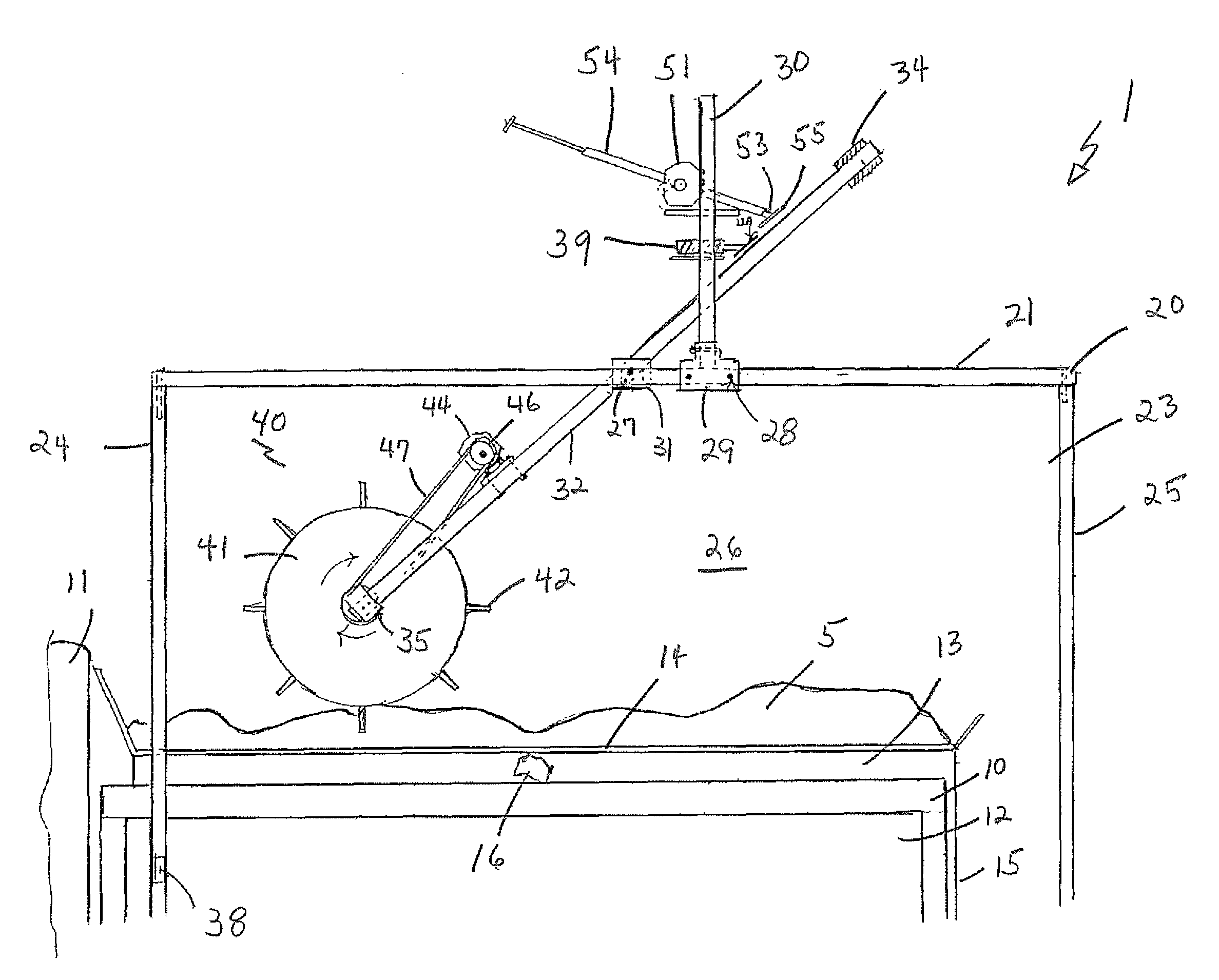
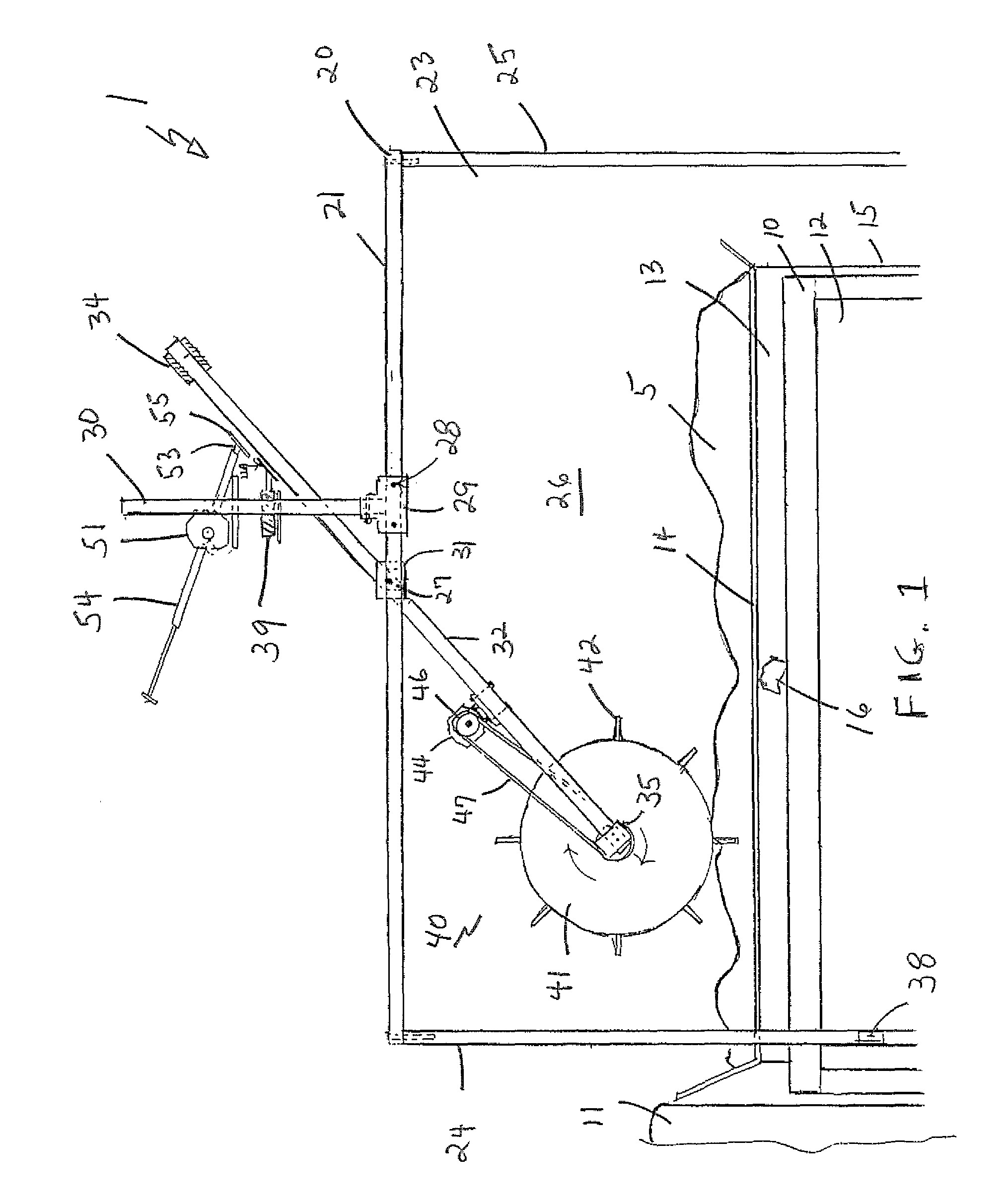
[0018]Referring to the drawings in detail wherein like elements are indicated by like numerals, there is shown a roller apparatus 1 comprised of a frame 20 holding a roller assembly 40, said frame adapted to accommodate a dump truck 10 within the frame interior. The truck 10 has a front cab 11, a rear dump body 12, and a granular dispenser 13 within the dump body 12 and extending rearward from the dump body 12. The dispenser 13 is adapted to hold a supply of granular material 5 within a dispenser interior 16 and dispensing said granular material 5 out a dispenser rear 15. The dispenser 13 has a screen 14 attached to the top of the dispenser. Granular material is loaded into the dispenser interior 16 through said screen 14.

[0019]The frame 20 has a generally rectangular shape with a top 21, a bottom 22, two opposite, parallel sides 23, an open front 24, and an open rear 25, said front and rear defining a frame, longitudinal axis, said top, bottom, front, rear, and sides defining a fra...


PUM


Abstract

A free-standing roller apparatus for clearing screens on dispensers sitting within truck dump bodies is provided. The roller apparatus provides a hard bristle, rotating roller attached to an arm, which allows the roller to be lowered onto the dispenser screen. The roller adjusts automatically to the height of each truck.

Description

BACKGROUND OF THE INVENTION[0001]This invention relates to screening machines, and more particularly to a roller for cleaning sand and gravel screens.[0002]Spreader / dump truck vehicles are well known in the art. Such vehicles are adapted especially for the purpose of spreading road salt and sand on winter roads as well as conventional dump truck purposes, such as transporting salt, sand and other granular materials. Trucks of this type typically contain a dispensing device that sits upon the dump body of the truck. To evenly spread road salt and sand, the granular material within the dispenser must be free of clumps and extraneous material. This is accomplished by attaching a screen, either temporarily or permanently, to the top of the dispenser, thereby providing a dispenser loaded with sifted granular material. To load the dispenser, granular material is poured onto and through the screen into the dispenser within the truck body. Clumped material as well as granular material which...

Claims


Application Information

Patent Timeline
IPC IPC(8): B07B1/50B07B1/04E01H10/00B07B1/52B07B1/00
CPCB07B1/50E01H10/007B07B1/04B07B1/524B07B13/16B60P1/28B07B1/005
Inventor PICARD, JR., CHARLES A.
Owner PICARD JR CHARLES A
Why Eureka
Try Eureka