System and method for crushing and compaction

a crushing and compaction technology, applied in the field of crushers, can solve the problems of increasing the amount of materials ending up in landfills, increasing the disposal cost, and increasing the liquid content of waste products, so as to reduce reliability, increase efficiencies and remedy problems, and constant back pressure

Active Publication Date: 2016-08-02
KOMAR IND LLC
View PDF74 Cites 1 Cited by
  • Summary
  • Abstract
  • Description
  • Claims
  • Application Information

AI Technical Summary

Benefits of technology

[0004]The liquid content of waste products creates multiple issues for retailers, landfills, and manufacturers. Liquid delivery to landfills is discouraged by landfills and, in some circumstances, loads with excessive liquids are refused. Waste haulers often charge retailers and manufacturers by the ton for transporting waste. Most liquids are very heavy, increasing disposal cost. Additionally, environmental fines for leaking waste are imposed on haulers trying to transport waste containing liquids. Recyclers desire product that includes minimal amounts of liquid delivered to them as it hinders their automated processing. Liquid is a detriment for waste destined to be utilized as a fuel as the transportation costs are increased and the aggregate BTU value of the material is reduced. Liquid is often the product of the manufacturer. Thus, separating the liquid and disfiguring the packaging reduces liability of the undesired or substandard product reaching the public.
[0005]Consumer packaging, such as plastic bottles and aluminum cans, contain large amounts of air when empty. Reducing the volume and increasing density of these products is desirable in order to make transportation and recycling more cost effective. Furthermore, the reduction of volume at the source makes storage requirements significantly more manageable.
[0007]There are currently five primary technologies utilized for compacting products and separating liquids. An exemplary embodiment of the invention provides increased efficiencies and remedies problems with known technologies, such as: Ram Compaction, Roll Compactors, Heat Extrusion, Screw Compactors with compression flights, and Screw Compactors with a powered adjustable restricting mechanism.
[0008]The existing screw compactors are inefficient in function as they utilize a powered restricting device to create back pressure against the material being crushed or extruded in order to flatten the product. The restricting mechanisms of known screw compactors also have some further drawbacks. The restricting mechanisms consume additional power, have multiple moving parts which reduce reliability, and provide constant back pressure that increases wear of the end of the screw assembly. In known screw compactors, the flattening of the product occurs as a result of restricting the flow of the mass of material being extruded. However, known restricting mechanisms commonly allow some full or partially full products, such as bottles, to remain unchanged in form (i.e., not crushed). This makes known technology ineffective for removing liquid. Furthermore, the constant need for back pressure of the extruded plug of material counteracts the compaction capabilities of known technology for continued conveyance or further compaction into a receiving container for densification for transport. The restricting mechanisms of known technologies create a divergence when trying to combine compaction with a liquid removal capability, resulting in a compactor that is impractical and inefficient.
[0010]Exemplary embodiments may include a screw crusher utilizing a cantilevered screw with an inverse tapered shaft with flighting for conveying the product up the length of the shaft for compression and an end flight providing thrust to the product for further conveyance beyond the end of the screw or additional compaction when utilized with a receiving container. An exemplary embodiment of the device may utilize a single moving element in relation to a cylindrical tube for compression of the product. Also, an exemplary screw compactor may utilize a fixed replaceable restrictor tube section and an efficient screw design making it more cost effective and efficient to operate than other known compactors. Furthermore, an example of the device may be fitted with perforated or the preferred “V” Slotted tube to perform liquid removal in addition to the compaction of the material.
[0012]Exemplary embodiments of the crusher may allow for substantially continuous use by minimizing or eliminating a buildup of solid material mass that could slow or stop the crusher.

Problems solved by technology

Furthermore, the amount of materials ending up in landfills is continuously increasing.
The liquid content of waste products creates multiple issues for retailers, landfills, and manufacturers.
Most liquids are very heavy, increasing disposal cost.
Recyclers desire product that includes minimal amounts of liquid delivered to them as it hinders their automated processing.
Consumer packaging, such as plastic bottles and aluminum cans, contain large amounts of air when empty.
Many times these labels may accumulate and back up or hinder the crusher during use.
The existing screw compactors are inefficient in function as they utilize a powered restricting device to create back pressure against the material being crushed or extruded in order to flatten the product.
The restricting mechanisms of known screw compactors also have some further drawbacks.
The restricting mechanisms consume additional power, have multiple moving parts which reduce reliability, and provide constant back pressure that increases wear of the end of the screw assembly.
This makes known technology ineffective for removing liquid.
Furthermore, the constant need for back pressure of the extruded plug of material counteracts the compaction capabilities of known technology for continued conveyance or further compaction into a receiving container for densification for transport.
The restricting mechanisms of known technologies create a divergence when trying to combine compaction with a liquid removal capability, resulting in a compactor that is impractical and inefficient.

Method used


Image

  • System and method for crushing and compaction
  • System and method for crushing and compaction
  • System and method for crushing and compaction

Examples


Embodiment Construction

)

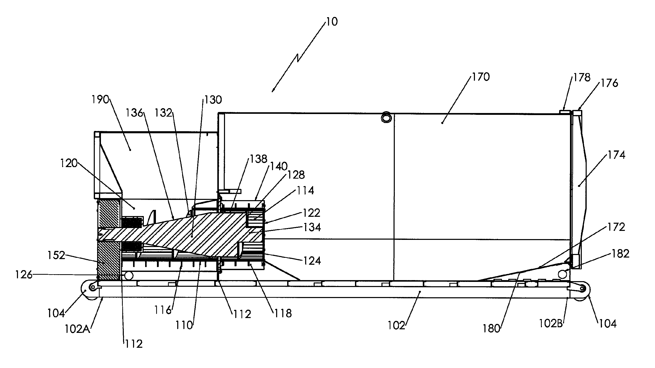
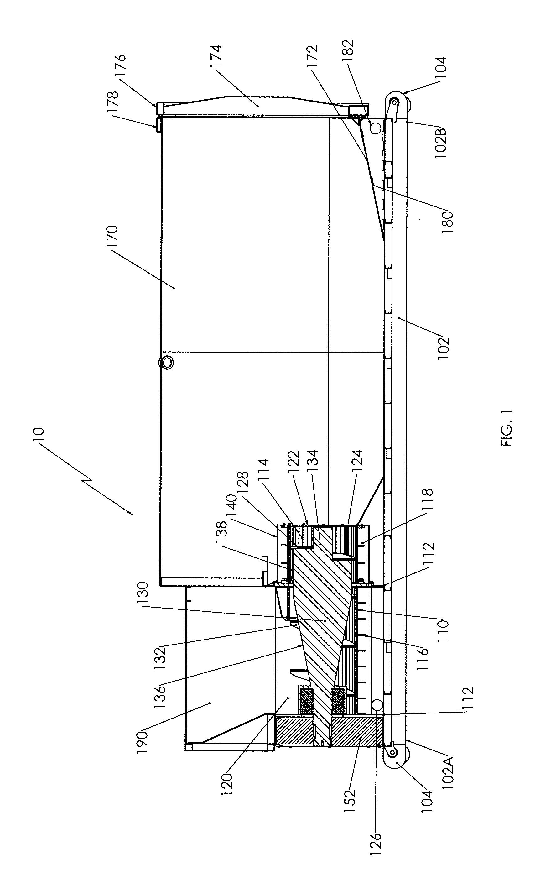
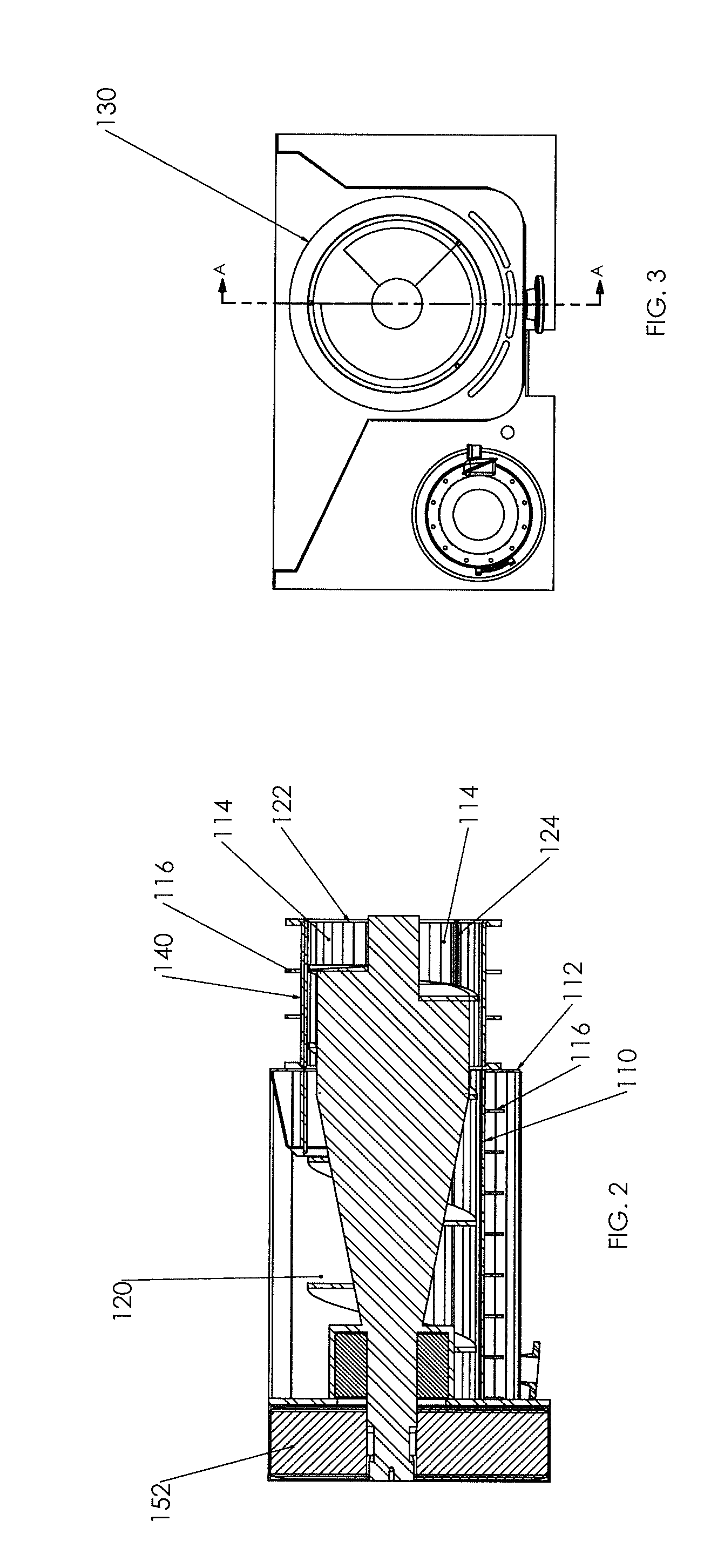
[0025]As seen in FIGS. 1-5, exemplary embodiments of a crusher 10 that may be adapted to compact plastics or other materials are illustrated. Exemplary embodiments may include a frame 102 with a proximal end 102A and a distal end 102B such that mounting bodies 104 are attached to the frame 102. In other exemplary embodiments, the frame 102 may be adapted to move on different surfaces with the inclusion of wheels, rollers, or other devices that are included with or exclusive of the mounting bodies 104 that would facilitate movement thereof.

[0026]Exemplary embodiments of the crusher 10 may include a compaction chamber 110 that may be mounted to the frame 102. The compaction chamber 110 may include one or more mounting bodies 112 that extend from the periphery thereof that facilitate mounting of the compaction chamber 110 with the frame 102. The compaction chamber 110 may be associated with the frame 102 by any number of means. However, in one example, threaded fasteners may facilitat...


PUM


Abstract

An exemplary embodiment of a screw crusher may utilize a cantilevered screw with an inverse tapered shaft with flighting for conveying the product up the length of the shaft for compression. The screw may include an end flight configured to provide thrust to the product for further conveyance beyond the end of the screw or additional compaction when utilized with a receiving container. An exemplary embodiment of the screw crusher may utilize a single moving element in relation to a cylindrical tube for compression of the product. Also, an exemplary screw compactor may utilize a fixed replaceable restrictor tube section and an efficient screw design making it more cost effective and efficient to operate than other known compactors. Furthermore, an example of the screw crusher may be fitted with perforated or the preferred “V” Slotted tube to perform liquid removal in addition to the compaction of the material.

Description

[0001]This application is a continuation-in-part of U.S. application Ser. No. 13 / 007,864, filed Jan. 17, 2011, which claims the benefit of U.S. Provisional Application No. 61 / 421,505, filed Dec. 9, 2010, each of which is hereby incorporated by reference as if fully recited herein.BACKGROUND AND SUMMARY OF THE INVENTION[0002]Exemplary embodiments of the invention are related to a crusher with the ability to compact. More particularly, exemplary embodiments may include a screw crusher that may facilitate the movement of compacted or compressed material better than known crushers.[0003]The amount of consumer products being brought to market with disposable packaging and products with a shelf life containing liquids have driven the market need for many different and more efficient methods of processing these products as they enter the waste stream. Furthermore, the amount of materials ending up in landfills is continuously increasing. As the scarcity of landfill space increases, along w...

Claims


Application Information

Patent Timeline
Patent Type & Authority Patents(United States)
IPC IPC(8): B30B9/14B30B9/30
CPCB30B9/3014B30B9/3042B30B9/3082B30B9/3089
Inventor KOENIG, MARK E.KOENIG, LARRY E.
Owner KOMAR IND LLC
Why Eureka
Try Eureka