Check patentability & draft patents in minutes with Patsnap Eureka AI!

Supporting unit structure of vehicle seat

a vehicle seat and support unit technology, applied in the direction of vehicle seats, vehicle components, vehicle arrangements, etc., can solve the problems of vehicle seats vibrating, and achieve the effects of preventing seat vibration, stably restricting excessive displacement of seat connected members, and reducing vibration

Inactive Publication Date: 2016-08-02
HONDA MOTOR CO LTD
View PDF20 Cites 1 Cited by
  • Summary
  • Abstract
  • Description
  • Claims
  • Application Information

AI Technical Summary

Benefits of technology

Effectively prevents seat vibrations and restricts excessive displacement without increasing space or weight, allowing for more flexible seat layout designs.

Problems solved by technology

Therefore, when a vibration having a frequency close to the natural frequency of the vehicle sheet is transmitted to the vehicle floor from an idling vibration of the engine or from driving vibration, it is likely to cause the vehicle seat to vibrate.

Method used


Image

  • Supporting unit structure of vehicle seat
  • Supporting unit structure of vehicle seat
  • Supporting unit structure of vehicle seat

Examples


Embodiment Construction

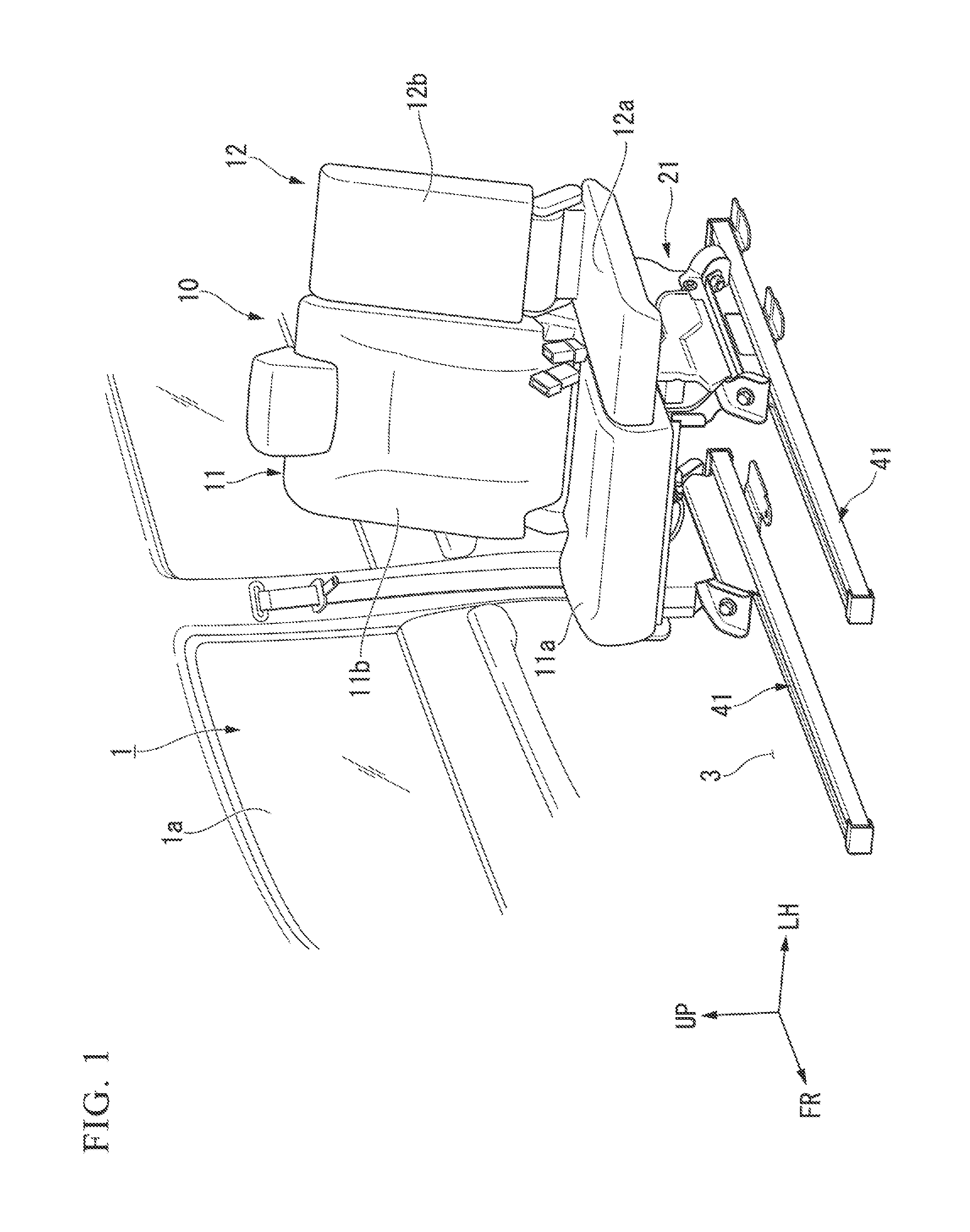
[0021]Hereinbelow, an embodiment of the present invention will be described with reference to the drawings. In the drawings, the arrow FR refers to the front of the vehicle 1. The arrow UP refers to the upper direction of the vehicle 1. The arrow LH refers to the left direction of the vehicle 1. In the following description, unless otherwise stated in particular, the terms front, rear, above, below, left, and right are intended to mean front, rear, above, below, left, and right with respect to the vehicle 1, respectively.

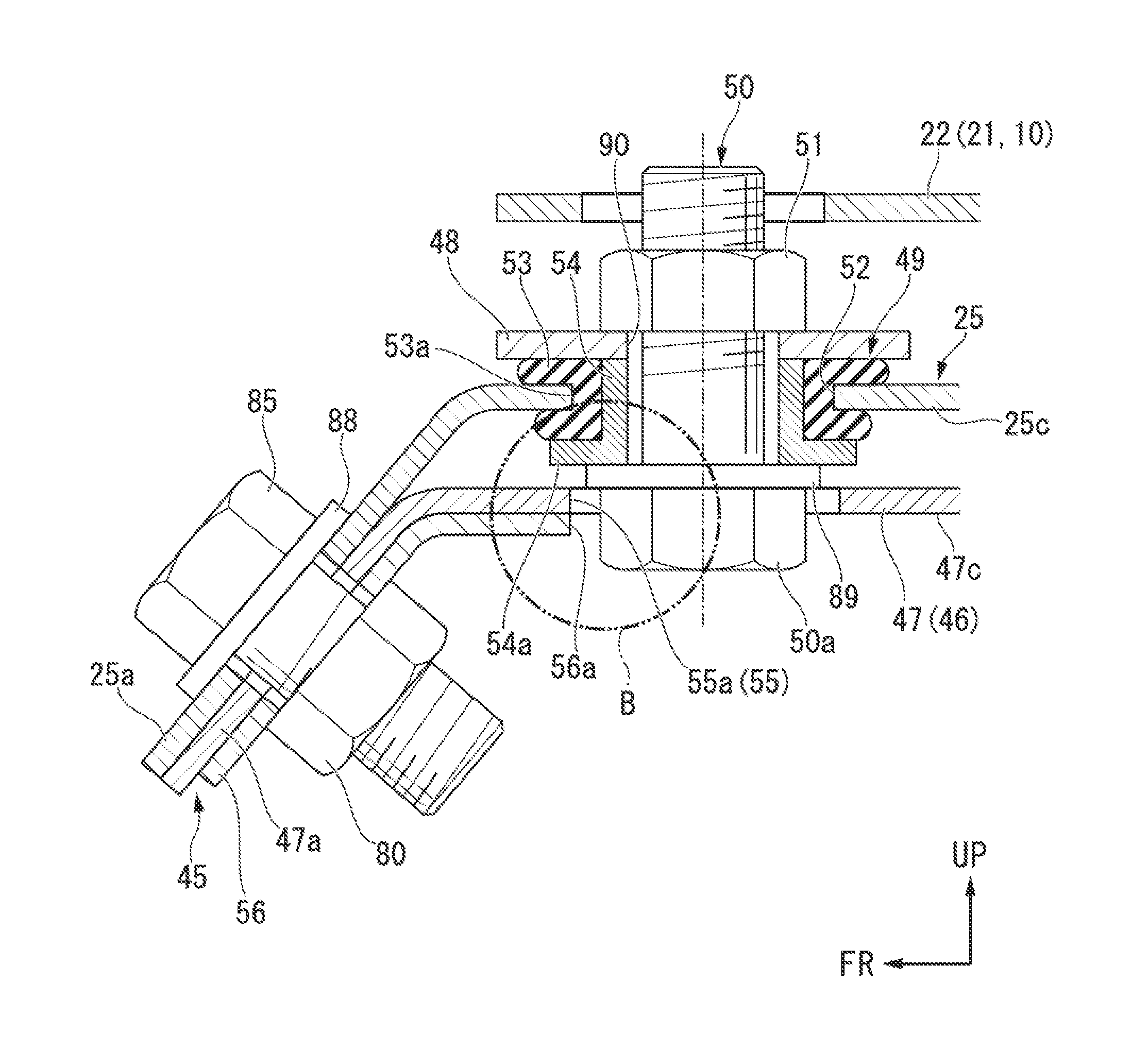
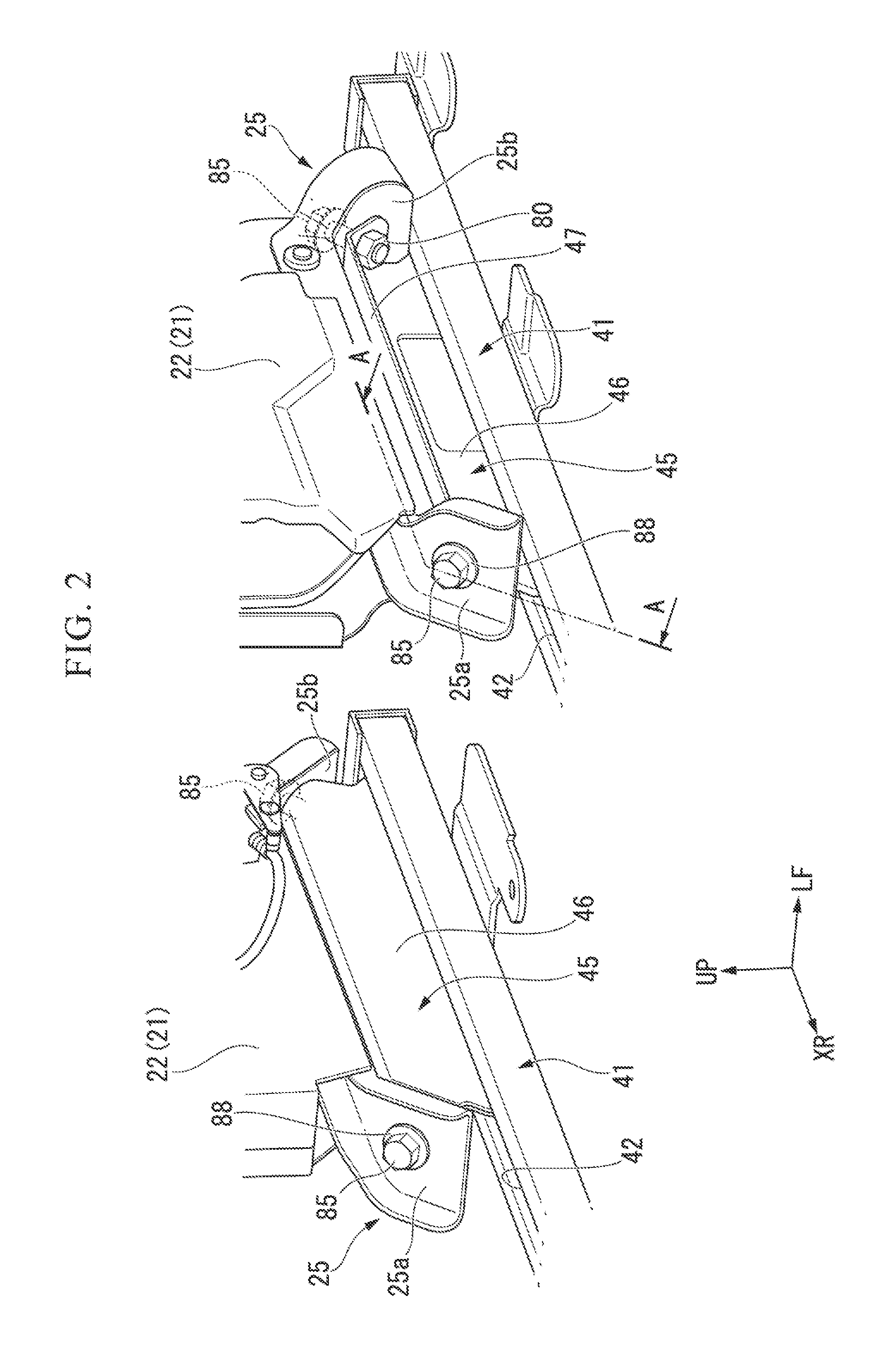
[0022]FIG. 1 is a diagram showing the vehicle seat 10 installed in the vehicle chamber 1a (hereinbelow, refer to “seat 10”) and the mounting portion of the seat. The vehicle 1 in this embodiment is a minivan type vehicle having multiple rows of seats in the front-rear direction on the floor 3 in the vehicle chamber 1a. In FIG. 1, only the seat 10 in the second row is shown. FIG. 2 is a diagram showing an enlarged part of FIG. 1. FIG. 3 is an exploded perspective vie...


PUM


Abstract

A supporting unit structure of a vehicle seat includes: a rubber elastic body; a seat-connected member; and a floor-connected member. An inner peripheral portion of the rubber elastic body is fastened to either one of the seat-connected member or the floor-connected member by a fastening member that penetrates the inner peripheral portion, and an outer peripheral portion of the rubber elastic body is fastened to the other one of the seat-connected member or the floor-connected member. The other one of the seat-connected member or the floor-connected member is provided with a stopper portion that abuts the fastening member in a radial direction of the fastening member when the seat-connected member and the floor-connected member are relatively displaced by more than a predetermined distance.

Description

FIELD OF THE INVENTION[0001]The present invention relates to a supporting unit structure of a vehicle seat Priority is claimed on Japanese Patent Application No. 2012-153031, filed Jul. 6, 2012, the content of which is incorporated herein by reference.RELATED ART[0002]Many vehicle seats are supported rigidly relative to the vehicle body floor. Vibrations of various frequencies are generated in the vehicle. Therefore, when a vibration having a frequency close to the natural frequency of the vehicle sheet is transmitted to the vehicle floor from an idling vibration of the engine or from driving vibration, it is likely to cause the vehicle seat to vibrate.[0003]Therefore, as the supporting unit structure of the vehicle seat to deal with the vibration described above, a structure is known (for example, refer to Patent Document 1) in which a rubber elastic body is interposed between a floor-connected member and a seat-connected member.[0004]In the supporting unit structure described in P...

Claims


Application Information

Patent Timeline
Patent Type & Authority Patents(United States)
IPC IPC(8): B60N2/00B60N2/07B60N2/54B60N2/015B60N2/50F16F15/08B60N2/90
CPCB60N2/502B60N2/544B60N2/0732B60N2/542B60N2/015B60N2/0155B60N2/01583
Inventor KONDO, TAKASHISATO, SHINOBUSARUWATARI, NAOYUKIYASUDA, HIROYUKIHONDA, TOMOYUKIKITSUGI, TOMOMI
Owner HONDA MOTOR CO LTD
Features
  • R&D
  • Intellectual Property
  • Life Sciences
  • Materials
  • Tech Scout
  • Unparalleled Data Quality
  • Higher Quality Content
  • 60% Fewer Hallucinations
Learn More