Three-way solenoid valve

a solenoid valve and three-way technology, applied in the direction of valve housing, valve operating means/release devices, transportation and packaging, etc., can solve the problem of inability to make the opening diameter of the second valve seat large, and achieve the effect of reducing reliably switching a refrigerant flow passage, and ensuring the diameter of the valve por

Active Publication Date: 2016-08-02
FUJIKOKI CORP
View PDF13 Cites 4 Cited by
  • Summary
  • Abstract
  • Description
  • Claims
  • Application Information

AI Technical Summary

Benefits of technology

[0009]The invention has been made in consideration of the above-mentioned circumstances, and an object of the invention is to provide a very reliable three-way solenoid valve that can reliably switch a refrigerant flow passage while ensuring a refrigerant flow rate even under a large-differential pressure environment without increasing the size of an electromagnetic coil and the like.
[0017]According to the three-way solenoid valve of the aspect of the invention, the valve body includes a conduction hole that communicates with a back pressure chamber formed on a side of the second valve element opposite to the second valve seat, a third valve seat that is positioned between the conduction hole and the second outlet, a third valve element that is movably disposed so as to approach and be separated from the third valve seat, a biasing member that biases the third valve element toward the third valve seat, and an actuating member that is interposed between the first valve element and the third valve element in order to actuate the third valve element in a direction in which the third valve element is separated from the third valve seat. When the first valve element is moved in the valve body by the electromagnetic actuator and approaches or is separated from the first valve seat, the third valve element approaches or is separated from the third valve seat by the actuating member or the biasing member, and differential pressure between the front and the rear sides of the second valve element is changed through the conduction hole, so that the second valve element approaches or is separated from the second valve seat. Accordingly, it is possible to ensure the diameter of the valve port that is formed at the second valve seat while reducing the diameter of the valve port that is formed at, for example, the third valve seat. For this reason, it is possible to reliably switch a refrigerant flow passage while ensuring a refrigerant flow rate even under a large-differential pressure environment without increasing the size of the electromagnetic coil and the like.
[0018]Further, a first valve chest in which the first valve element is disposed and a second valve chest in which the second valve element is disposed are disposed side by side in a lateral direction, the first valve chest and a third valve chest in which the third valve element is disposed are disposed side by side in a longitudinal direction, and the conduction hole, which allows the third valve chest and the back pressure chamber of the second valve chest to communicate with each other, is disposed so as to be inclined. Accordingly, there is also an advantage of simplifying a process for manufacturing the three-way solenoid valve while reducing the physical size of the three-way solenoid valve.

Problems solved by technology

For this reason, there is a problem in that an opening diameter of the second valve seat cannot be made large.

Method used


Image

  • Three-way solenoid valve
  • Three-way solenoid valve
  • Three-way solenoid valve

Examples


Embodiment Construction

[0023]A three-way solenoid valve according to an embodiment of the invention will be described below with reference to the drawings.

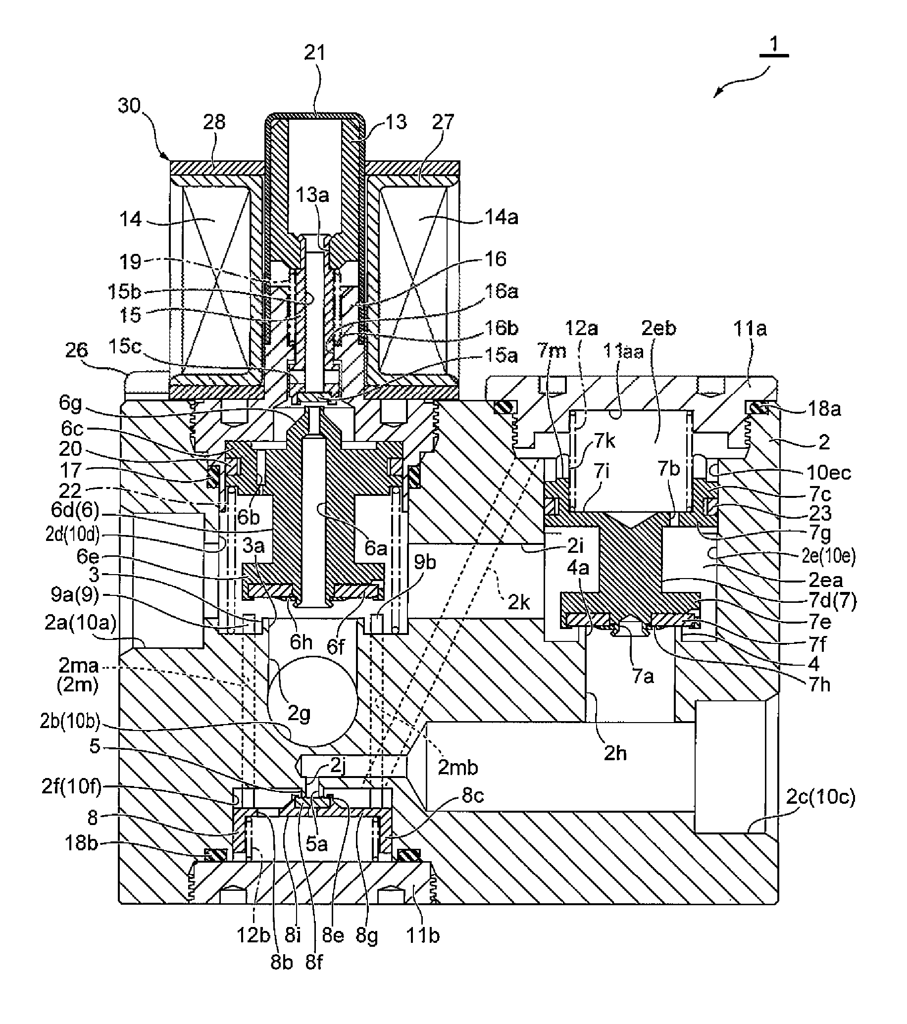
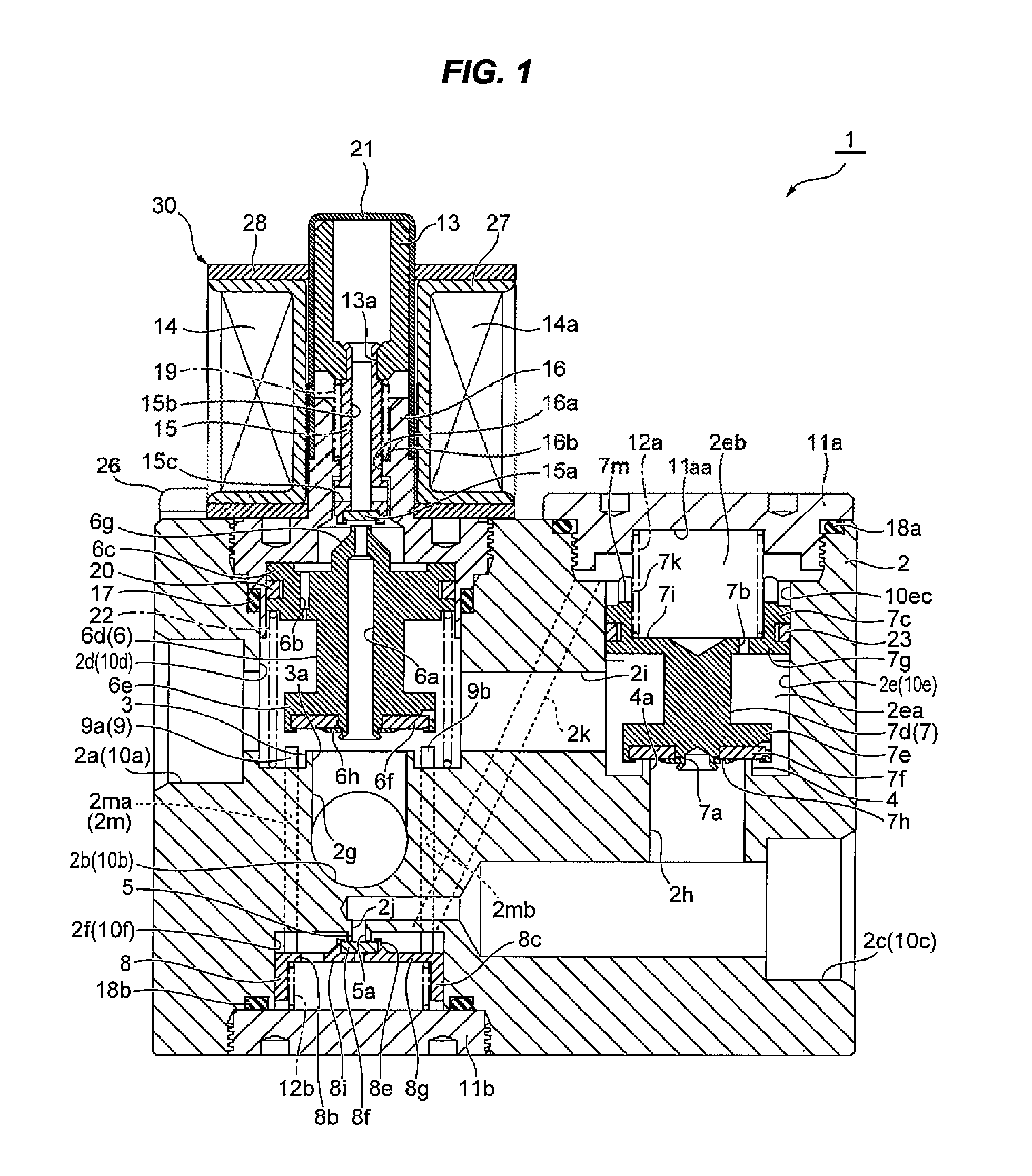
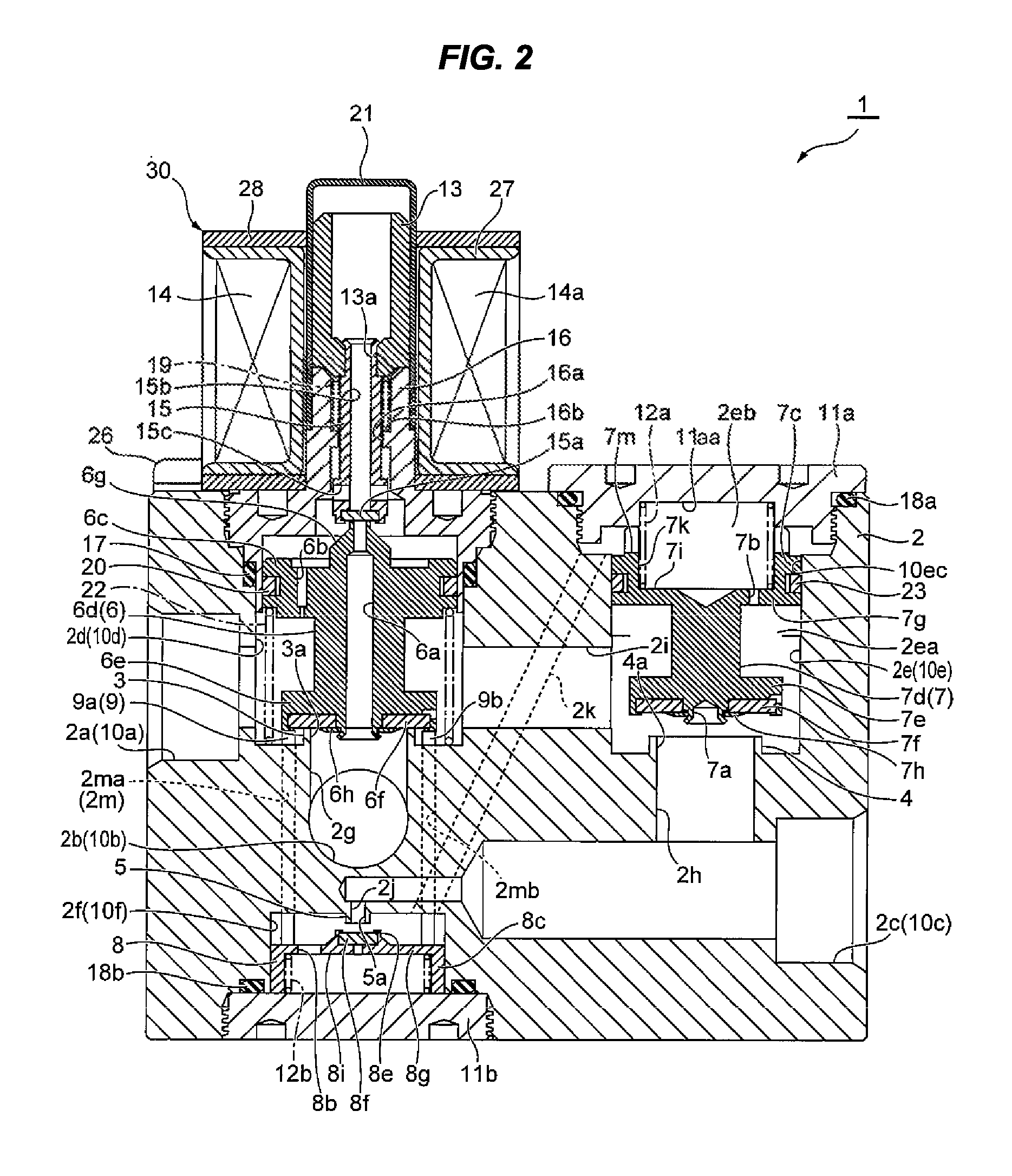
[0024]FIGS. 1 and 2 are longitudinal sectional views of a three-way solenoid valve according to an embodiment of the invention, and are views illustrating a state in which current is not applied to an electromagnetic coil and a state in which current is applied to the electromagnetic coil.

[0025]The entire structure of the three-way solenoid valve according to the embodiment of the invention will be described first. The illustrated three-way solenoid valve 1 mainly includes a valve body 2 that is made of, for example, metal, piston-type first to third valve elements 6 to 8, and an electromagnetic actuator 30 that is driven to move the first valve element 6 up and down by an electromagnetic force.

[0026]The valve body 2 is provided with an inlet 2a, a first outlet 2b, a second outlet 2c, a first valve seat 3 that is positioned between the inlet 2a and the ...


PUM


Abstract

There is provided a very reliable three-way solenoid valve that can reliably switch a refrigerant flow passage while ensuring a refrigerant flow rate even under a large-differential pressure environment without increasing the size of an electromagnetic coil and the like.A valve body includes a conduction hole that communicates with a back pressure chamber formed on a side of a second valve element opposite to a second valve seat, a third valve seat that is positioned between the conduction hole and a second outlet, a third valve element that is movably disposed so as to approach and be separated from the third valve seat, a coil spring that biases the third valve element toward the third valve seat, and actuating rods that are interposed between a first valve element and the third valve element.

Description

BACKGROUND OF THE INVENTION[0001]1. Field of the Invention[0002]The present invention relates to a three-way solenoid valve, and more particularly, to a three-way solenoid valve that is suitable to switch a refrigerant flow passage in a heat pump device of, for example, a heating and cooling system and the like.[0003]2. Description of the Related Art[0004]In the past, a three-way solenoid valve disclosed in JP 2012-002282 A has been known as this kind of a three-way solenoid valve.[0005]As illustrated in FIGS. 3 and 4, the three-way solenoid valve 1′ in the related art includes: a valve body 2′ that includes one inlet 2a′, first and second outlets 2b′ and 2c′, and valve chests 2d′ and 2e′; first and second valve seats 3′ and 4′ that are positioned in the valve body 2′; first and second valve elements 6′ and 7′ that approach and are separated from these valve seats 3′ and 4′ and allow the inlet 2a′ and the outlets 2b′ and 2c′ to communicate with each other; actuating rods 9′ (9a′, 9b...

Claims


Application Information

Patent Timeline
Patent Type & Authority Patents(United States)
IPC IPC(8): F16K31/40F16K11/16F16K31/06
CPCF16K31/0624F16K31/406F16K31/408F16K11/161Y10T137/86879Y10T137/7832Y10T137/777Y10T137/7766Y10T137/87877Y10T137/7769Y10T137/7835Y10T137/87772F16K11/048F16K31/06F16K31/0603F16K11/10F16K27/00
Inventor KAINUMA, HIROSHIHAYASAKA, MASASHIKOJIMA, YASUSHI
Owner FUJIKOKI CORP
Why Eureka
Try Eureka