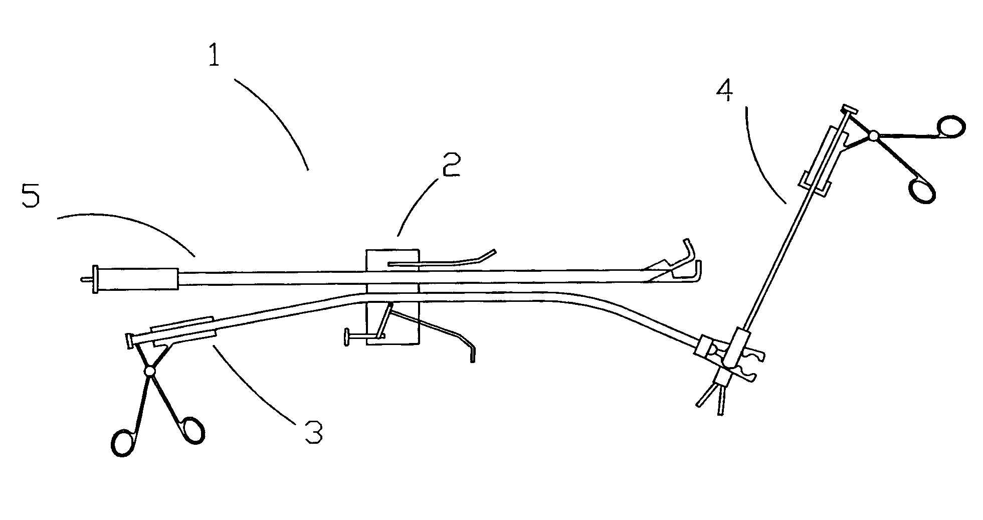
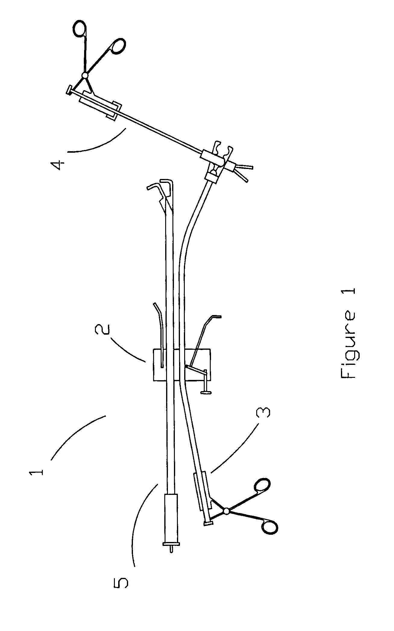
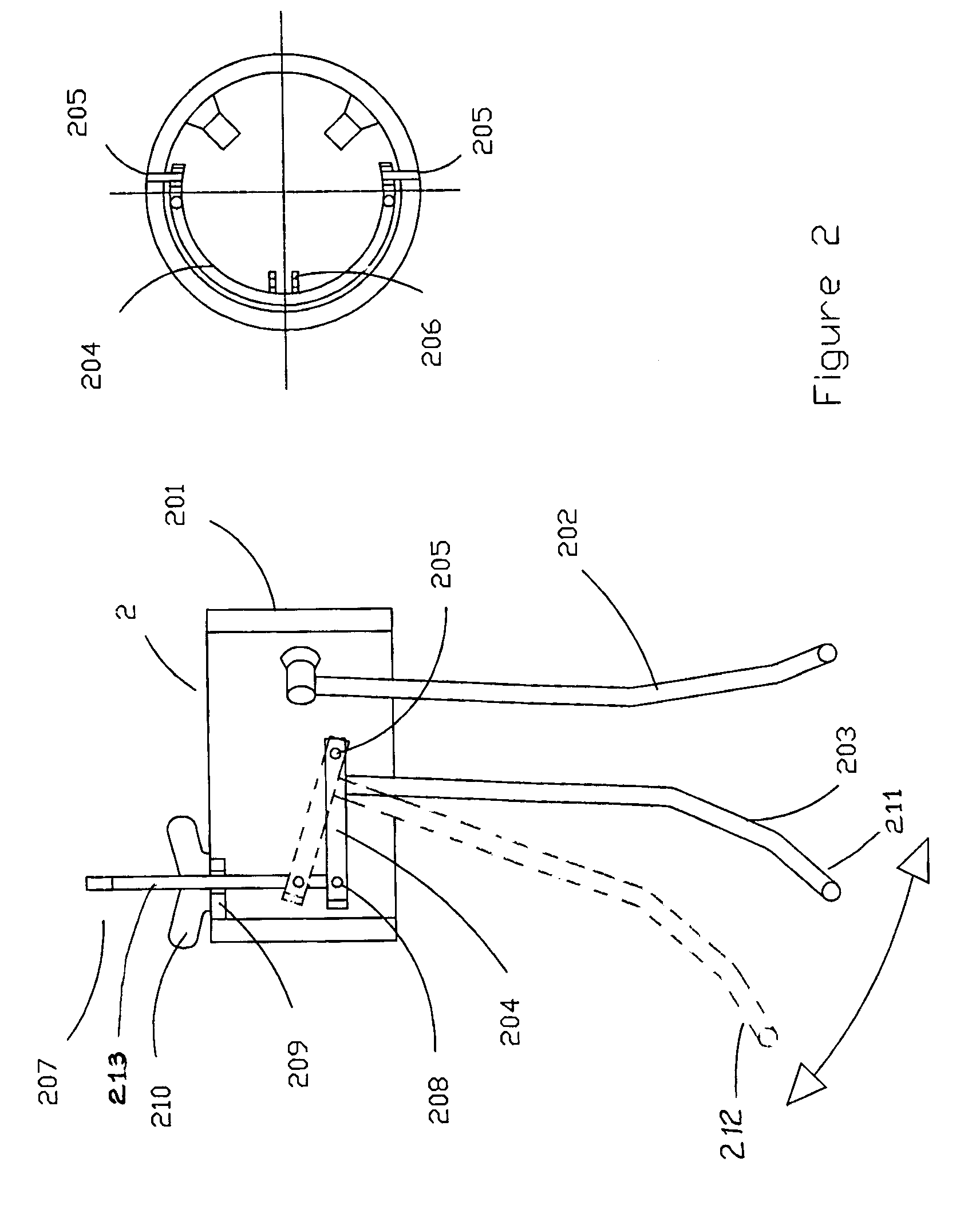
Surgical instrument equipment appropriate for mini-invasive surgery
a surgical instrument and mini-invasive technology, applied in the field of surgical instrument equipment, can solve the problems of not being able to adjust to the different needs of variable angulation
- Summary
- Abstract
- Description
- Claims
- Application Information
AI Technical Summary
Benefits of technology
Problems solved by technology
Method used
Image
Examples
first embodiment
[0048]In a first embodiment, the driving element of the clamp tips is of double articulation, as seen in FIGS. 4B and 4C. The double articulation is made up by a pair of clamp tips (428) joined by bolts to a pair of clamp articulations (426). The clamp articulations are flat elements, with thru holes on each of their ends. A first bolt (425) joins the orifices of proximal ends of the clamp articulations to the driving intrahead device by means of its distal thru hole. The clamp tips have a first thru hole at their proximal ends and a second thru hole in the middle of said tips and the first hole. Both clamp tips are joined by means of second bolts (429) at their proximal ends to the distal ends of the clamp articulations. By means of a third bolt (430) at its second holes, they are joined to the body of working head (427). This set of elements make up an articulation which, when receiving the bi-directional movement of the driving intrahead device (422), causes the opening and closu...
second embodiment
[0049]In a second embodiment, the driving element of the clamp tips is a single articulation, as seen in FIG. 4D. The body of working head (427) has a complete circumference (434) at its proximal end, the rest being only the basis (435). In the middle of the basis, a pair of flanges (436) opposite to a thru hole are provided. Between said pair of flanges, the proximal end of the single articulation (437) is lodged, which has a first thru hole, and this single articulation is joined by a bolt (438) to the pair of flanges (436). Near this first thru hole, a second thru hole is provided to which the distal end of the driving intrahead device is joined, by means of a bolt (439), and through a joining element (440). In this embodiment, a joining element (440) is provided between said driving intrahead device (422) and the single articulation (437). This joining element is joined to the driving intrahead device and, at its distal end, a thru hole is provided, where the bolt is coupled (43...
third embodiment
[0050]In a third embodiment, the driving element of the clamp tips is an elastic type articulation, as seen in FIG. 4E. The body of working head (427) has, at its proximal end, an internal thread (443) that finishes, at its distal end, in tubular shape. By the interior of the head, the driving intrahead device (422) moves freely, having, at the proximal side, an orifice (423) with internal thread (424) where the extenal thread (408) of the connecting needle (403) is coupled. Following the internal thread and in distal direction of the bolt, the latter is divided into two elastic, “V” shaped branches (441), forming the clamp tips. Each of these “V” shaped branches finishes in the form of a clamp to perform pression, dissection, cutting, clipping, separating, suturing, cauterizing, etc. When the driving chuck is displaced in bi-directional movement (from proximal to distal or vice versa), given the elastic feature of the “V” shaped branches, the latter are driven apart or put together...
PUM
 Abstract
Description
Claims
Application Information
 - R&D
- Intellectual Property
- Life Sciences
- Materials
- Tech Scout
- Unparalleled Data Quality
- Higher Quality Content
- 60% Fewer Hallucinations
Browse by: Latest US Patents, China's latest patents, Technical Efficacy Thesaurus, Application Domain, Technology Topic, Popular Technical Reports.
© 2025 PatSnap. All rights reserved.Legal|Privacy policy|Modern Slavery Act Transparency Statement|Sitemap|About US| Contact US: help@patsnap.com


