High-voltage capacitor charging device based on super-capacitor cascading

A technology of supercapacitors and high-voltage capacitors, which is applied in the direction of battery circuit devices, circuit devices, electrical components, etc., can solve the problems of system volume, cost increase, and failure rate increase, so as to save volume and cost, reduce charging current, and failure rate. low rate effect

Active Publication Date: 2015-08-26
INST OF ELECTRICAL ENG CHINESE ACAD OF SCI
View PDF3 Cites 3 Cited by
  • Summary
  • Abstract
  • Description
  • Claims
  • Application Information

AI Technical Summary

Problems solved by technology

In order to avoid this situation, the simple method is to divide large-capacity high-voltage capacitors into multiple groups and charge them separately. However, this method must connect high-voltage and high-current switches in series at the output end of each group of high-voltage capacitors, which also increases the size and cost of the system. increased rate

Method used


Image

  • High-voltage capacitor charging device based on super-capacitor cascading
  • High-voltage capacitor charging device based on super-capacitor cascading
  • High-voltage capacitor charging device based on super-capacitor cascading

Examples


Embodiment Construction

[0025] The present invention will be described in detail below in conjunction with the accompanying drawings and specific embodiments.

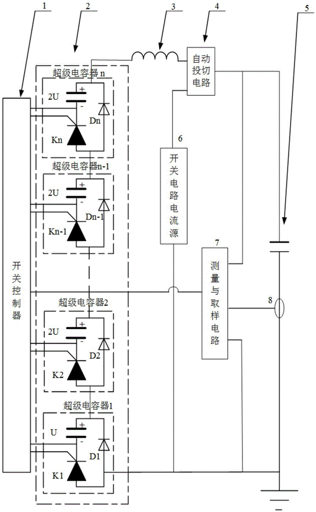
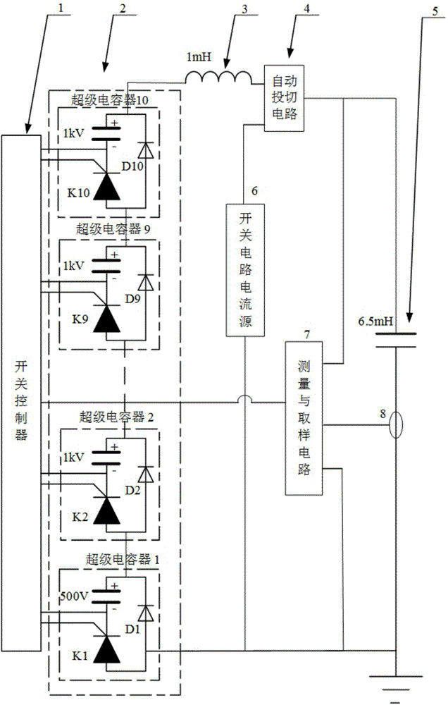
[0026] Such as figure 1 As shown, the high-voltage capacitor charging device of the present invention is composed of 8 parts: control system 1, supercapacitor bank cascade system 2, current-limiting inductor 3, automatic switching circuit 4, high-voltage capacitor 5, switching circuit current source 6, measurement and Sampling circuit 7, current measuring coil 8.

[0027] The high-voltage side of the supercapacitor bank cascading system 2 is connected in series with the current-limiting inductor 3 and then connected to the No. 1 input terminal of the automatic switching circuit 4, and the low-voltage side of the supercapacitor cascading system 2 is grounded; each unit in the supercapacitor bank cascading system 2 Lead out two ends respectively: the negative end of the supercapacitor and the trigger end of the IGBT, which are respectively conne...


PUM


Abstract

The invention discloses a high-voltage capacitor charging device based on super-capacitor cascading. A high-voltage end of a super-capacitor bank cascading system (2) is in series connection with a current-limiting inductor (3), and then is connected with a first input end of an automatic switching circuit (4). Two leading-out ends of each unit in the super-capacitor bank cascading system (2) are connected with an input end of a switching controller (1). A second input end of the automatic switching circuit (4) is connected with the positive electrode of a switching circuit current source (6). The output end of the automatic switching circuit (4) is connected with a high-voltage end of a high-voltage capacitor (5). A low-voltage end of the high-voltage capacitor (5) is grounded through a current measuring coil (8). A voltage input positive end of a measurement and sampling circuit (7) is connected with the output end of the automatic switching circuit (4). A current input end of the measurement and sampling circuit (7) is connected with the current measuring coil (8). The output end of the measurement and sampling circuit (7) is connected with the switching controller.

Description

technical field [0001] The invention relates to a high-voltage capacitor charging device. Background technique [0002] The electric spark source is a device for exploring geological conditions through the discharge of a high-voltage capacitor. The voltage range of the high-voltage capacitor is 1KV and above, and a high-voltage power supply is required to charge it. The initial method was to boost and rectify the 220V or 380V power grid voltage through a power frequency transformer to form a high-voltage power supply to charge the high-voltage capacitor. Later, it developed into a high-frequency switching technology to reduce the size of the power frequency transformer. The primary energy sources of the charging power supply are generally grid electric energy and diesel generators, but in mountainous areas, the above two primary energy sources are limited. With the development of supercapacitor technology, it is possible to provide initial energy by supercapacitors, and sup...

Claims


Application Information

Patent Timeline
Patent Type & Authority Applications(China)
IPC IPC(8): H02M3/06
CPCH02J7/345
Inventor 高迎慧樊爱龙孙鹞鸿徐旭哲
Owner INST OF ELECTRICAL ENG CHINESE ACAD OF SCI
Why Eureka
Try Eureka