Composite panel

a composite wall and panel technology, applied in the field of composite wall panels, can solve the problems of difficult construction of smooth joints between plywood substrates of adjacent panels, easy water damage to substrates, and prone to rigidity, and achieve the effect of greater rigidity of composite wall panels

Active Publication Date: 2016-08-09
IMPACT GUARD LLC
View PDF18 Cites 18 Cited by
  • Summary
  • Abstract
  • Description
  • Claims
  • Application Information

AI Technical Summary

Problems solved by technology

However, plywood substrates are susceptible to water damage, surface inconsistencies such as knots, irregular grain, etc., and joints between the plywood substrates of adjacent panels can be difficult to construct smoothly.
These wall panels work well for planar wall sections, but tend to be fairly rigid.
Difficulties can arise when using such wall sections in the front portions of trailers, recreational vehicles, etc., where it is often desirable to curve the wall, for example, where the top of a wall section joins an opposing roof panel.
Attempts have been made to add more flexible top sections to such wall panels, which lead to additional manufacturing complexity, joints in the panels and subsequent cost increases.

Method used


Image

  • Composite panel
  • Composite panel
  • Composite panel

Examples


Embodiment Construction

[0013]Reference will now be made in detail to presently preferred embodiments of the invention, one or more examples of which are illustrated in the accompanying drawings. Each example is provided by way of explanation, not limitation, of the invention. In fact, it will be apparent to those skilled in the art that modifications and variations can be made in the present invention without departing from the scope and spirit thereof. For instance, features illustrated or described as part of one embodiment may be used on another embodiment to yield a still further embodiment. Thus, it is intended that the present invention covers such modifications and variations as come within the scope of the appended claims and their equivalents.

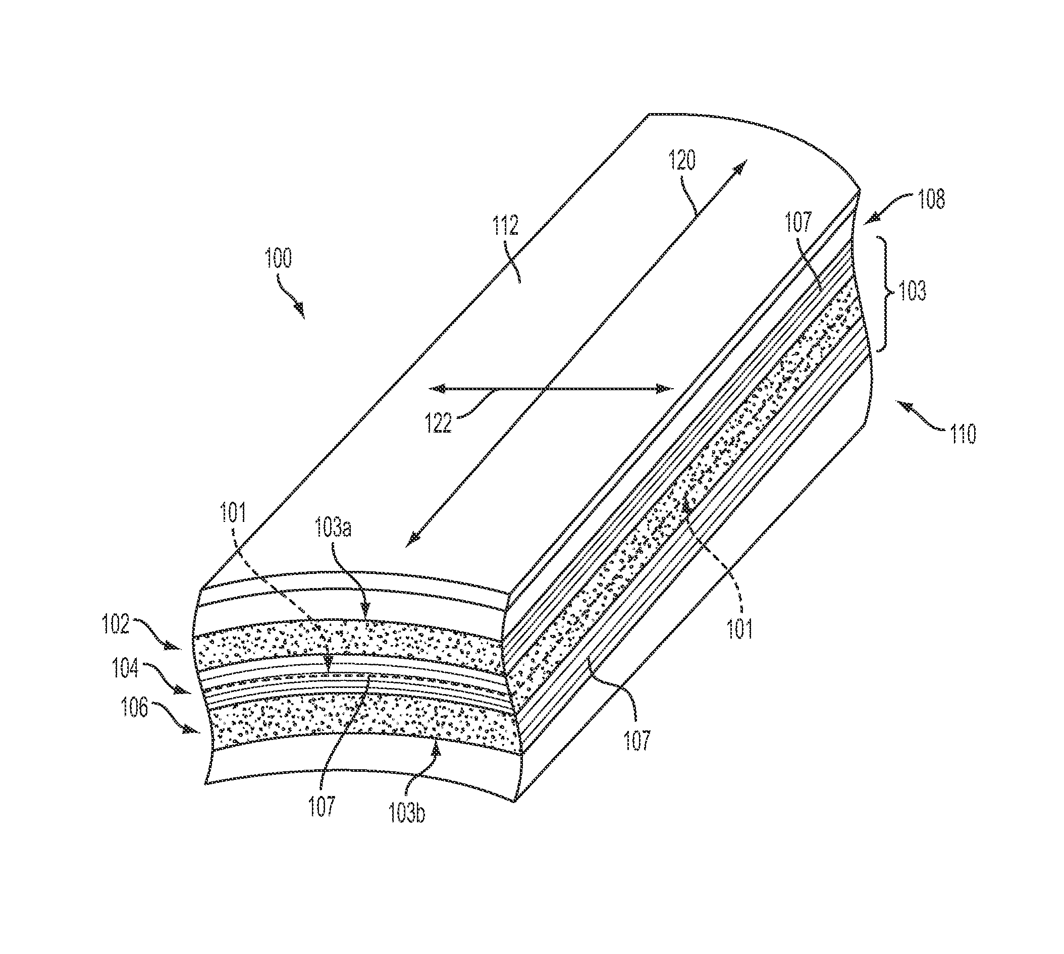
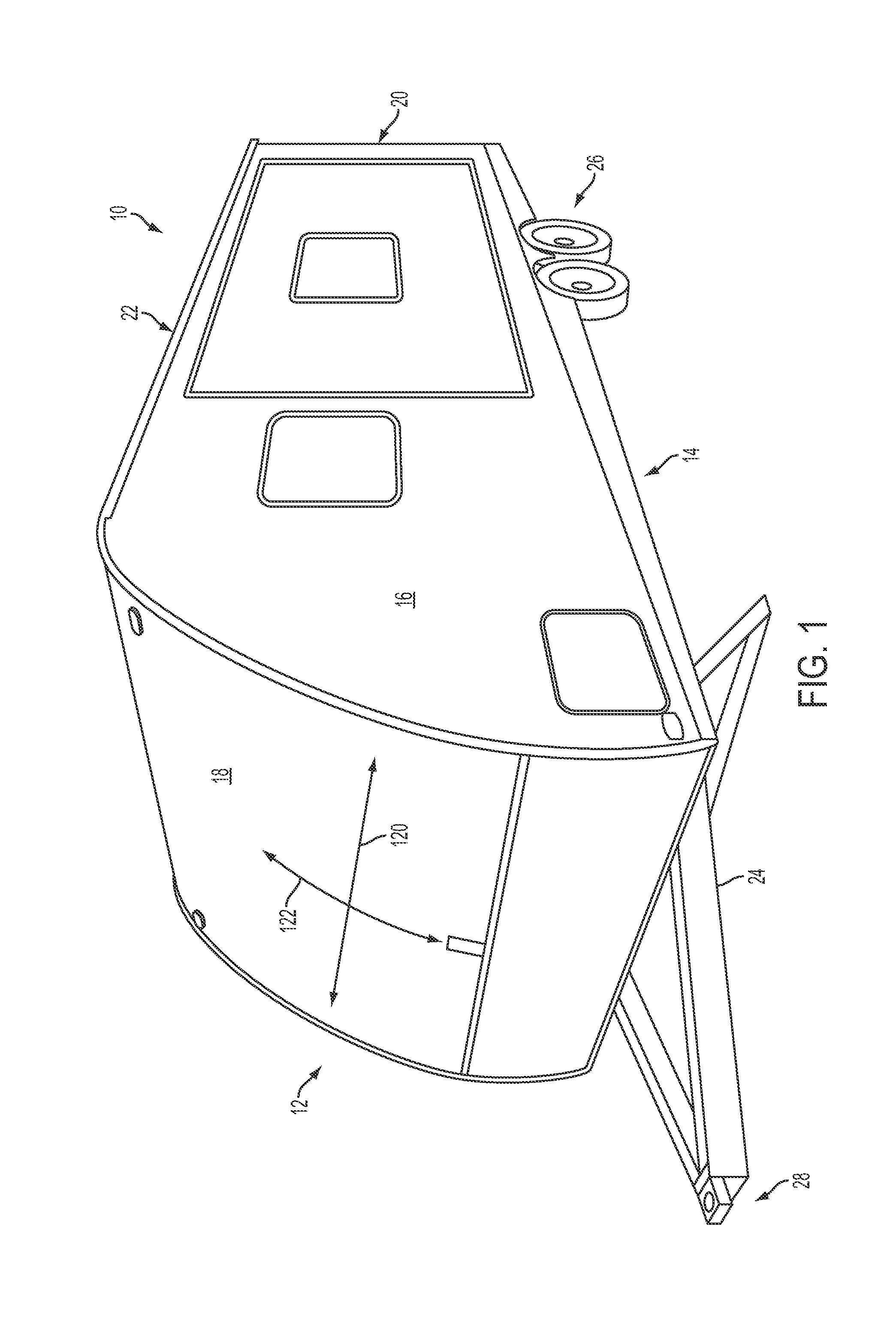
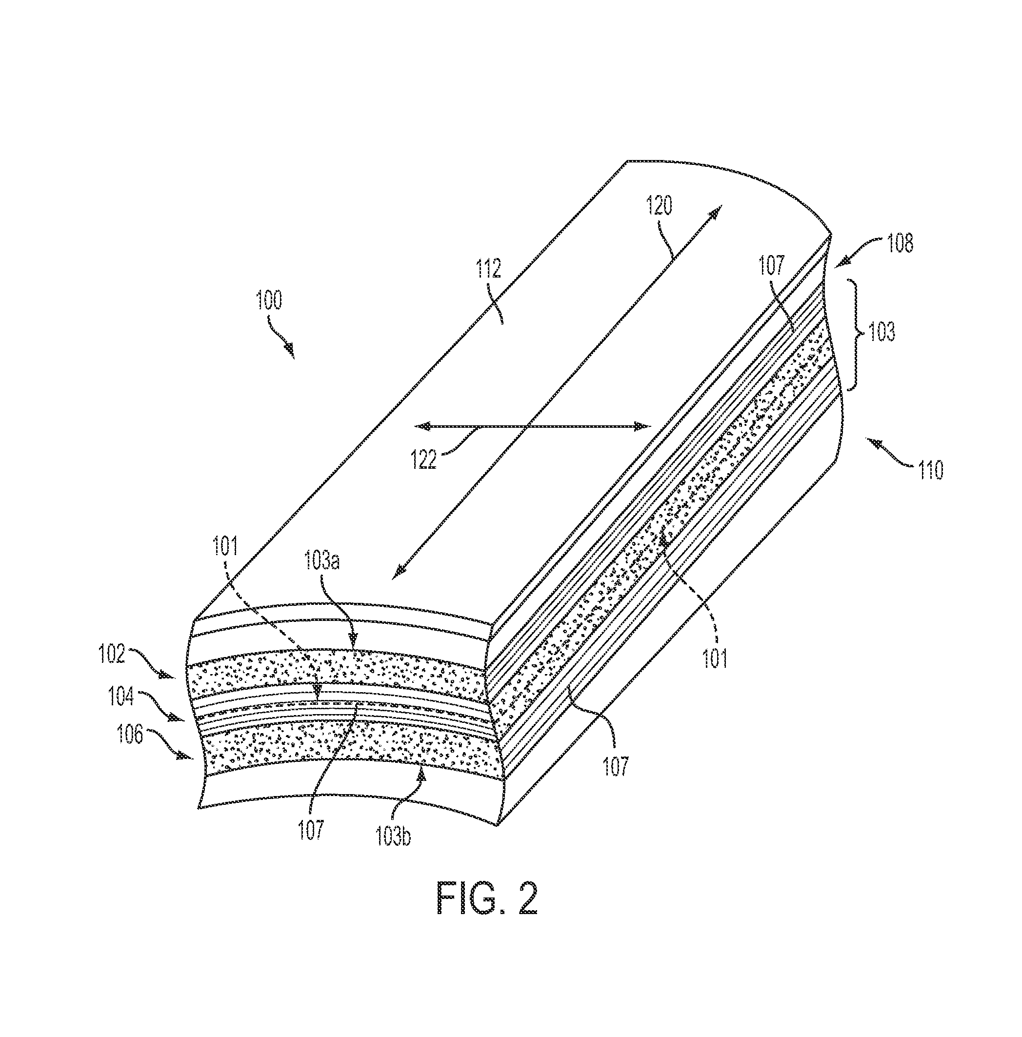
[0014]Referring now to the Figures, FIG. 1 shows a recreational vehicle, specifically a trailer 10, in which composite wall panels (FIGS. 2 and 3) constructed in accordance with an embodiment of the present disclosure are used. As shown, trailer 10 includes ...


PUM

PropertyMeasurementUnit
temperatureaaaaaaaaaa
rigidityaaaaaaaaaa

Abstract

A composite wall panel for use in vehicles having a floor structure and a front wall, the composite wall panel including a first polymer resin layer having a plurality of unidirectional fibers embedded therein that are substantially parallel to a first axis, and a second polymer resin layer having a plurality of unidirectional fibers embedded therein that are substantially parallel to a second axis, the second polymer resin layer being bonded to the first polymer resin layer so that the second axis is substantially perpendicular to the first axis. The composite wall panel is disposed so that the first axis is substantially parallel to the floor structure, and the rigidity of the composite wall panel is greater along the first axis than the second axis.

Description

FIELD OF THE INVENTION[0001]The present invention relates generally to a composite panel having a greater degree of rigidity along a first axis than along a second axis that is perpendicular to the first axis.BACKGROUND OF THE INVENTION[0002]It is known to use wall panels having a thin outer sheet of fiberglass when constructing walls of various vehicles such as recreational vehicles, trailers, mobile homes, etc., because the thin fiberglass sheet presents an aesthetically pleasing surface. For example, one such wall panel consists of the fiberglass sheet adhered to a plywood substrate, such as by gluing. However, plywood substrates are susceptible to water damage, surface inconsistencies such as knots, irregular grain, etc., and joints between the plywood substrates of adjacent panels can be difficult to construct smoothly. As well, other known wall panels may have outer surfaces formed by other materials such as, but not limited to, polymer films, aluminum, etc.[0003]Another known...

Claims


Application Information

Patent Timeline
Patent Type & Authority Patents(United States)
IPC IPC(8): B62D29/04
CPCB62D29/043B32B27/00B32B39/00B60P3/32B32B37/1027B32B37/1207B32B37/203B32B2262/101B32B5/02B32B5/024B32B5/26B32B27/36B32B27/40B32B2260/021B32B2260/046B32B2307/546B32B2307/732B32B2607/00B32B5/12B32B7/12B32B17/067B32B27/12B32B2605/00B32B27/32
Inventor OSTEN, SAMUEL J.
Owner IMPACT GUARD LLC
Why Eureka
Try Eureka