Tubular electrochemical cell

a technology of electrochemical cells and tubular plates, applied in the direction of electrochemical generators, electrolytic organic production, instruments, etc., can solve the problems of uneven pressure in the mea, bending stress, heat generation, etc., to reduce bending stress in the end plate, improve heat extraction, and uniform pressure

Inactive Publication Date: 2016-08-09
ITM POWER (RES) LTD
View PDF15 Cites 0 Cited by
  • Summary
  • Abstract
  • Description
  • Claims
  • Application Information

AI Technical Summary

Benefits of technology

[0010]The present invention is based on the realisation that a tubular / cylindrical membrane electrode assembly (MEA) has many benefits. Those benefits include reduced bending stresses in end plates (or interfaces between cells in a stack), uniform pressure throughout the MEA, improved heat extraction, ease of servicing of cells and MEAs within a stack, reduced sensitivities to components and assembly tolerances.

Problems solved by technology

The electron transfer, ion transfer and gas evolution processes are characterised by “overvoltages” (inefficiencies), and these result in heat generation.
This requires a significant set of ‘balance of plant’ (BoP) technologies, which tends to make an electrolyser system complex and expensive.
This leads to uneven pressure in the MEA and bending stresses.
This leads to further compressive stresses, which can cause failure of the cell.
A significant problem also exists with the servicing of planar electrolysers in a stack.

Method used


Image

  • Tubular electrochemical cell
  • Tubular electrochemical cell
  • Tubular electrochemical cell

Examples


example 1

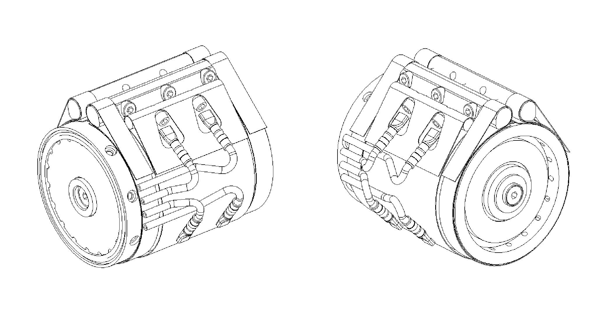
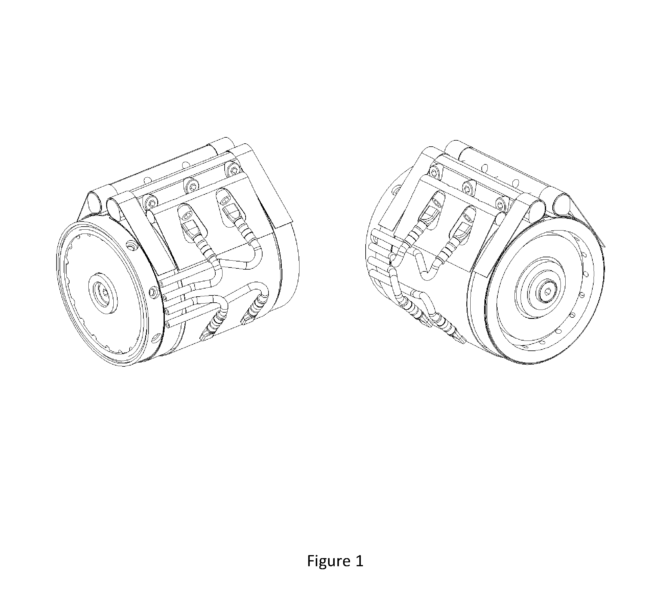
[0132]A tubular cell was made according to FIG. 1, and using the following components:[0133]Coaxial / tubular electrolyser running in a tower of water, without cooling water[0134]Anode: 1 micron Pt on Ti[0135]Cathode: Ni Cr[0136]Membrane material: Cationic hydrophilic ionic polymer membrane coated with 1 mg Pt / cm2 per side.[0137]Hydrated in the device[0138]Active area: 137 cm2-141 cm2 [0139]Membrane thickness: 0.4-0.45 mm[0140]Torque on active area tightening screws 3 Nm[0141]No cooling water circulated[0142]Temperature: 25 to 28° C.

[0143]The device was run successfully as an electrolyser up to 1 A / cm2.

example 2

[0144]Current density was plotted against voltage for an evaluation test electrolyser cell according to the invention (9 cm2) and a coaxial stack of electrolyser cells according to the invention (175 cm2). The plots were almost identical, showing that electrical resistive losses associated with the higher current in stacks are negligible. Additionally, the additional connections in the stack do not cause problematic voltage rise. This also proves the ability to maintain good appropriate and even contact pressure across the surface of the MEA, this homogenous pressure ability is backed up by pressure sensitive paper testing.

example 3

[0145]A 5-cell electrolyser stack according to the invention was constructed, with an active area of 150 cm2, an anode of 1 μm pt on Ti, a cathode of Ni Cr, and a hydrophilic polymeric membrane of thickness 0.6 mm.

[0146]A graph was plotted of cell position vs voltage and it was found that there was no detrimental voltage rise linked to cartridge position.


PUM

PropertyMeasurementUnit
pressuresaaaaaaaaaa
pressuresaaaaaaaaaa
shore hardnessaaaaaaaaaa

Abstract

A membrane electrode assembly (MEA) comprises substantially concentric and tubular-shaped layers of a cathode, an anode and an ion-exchange membrane. The MEAs of the invention can be used in an electrochemical cell, which comprises the following layers which are tubular-shaped, arranged substantially concentrically, and listed from the inner layer to the outer layer; (i) a cylindrical core; (ii) one of the electrodes; (iii) a membrane; (iv) the other of the electrodes; and (v) an outer cylindrical sleeve.

Description

CROSS REFERENCE TO A RELATED APPLICATION[0001]This application is a National Stage Application of International Application Number PCT / GB2010 / 051548, filed Sep. 15, 2010; which claims priority to Great Britain Application No. 0916179.5, filed Sep. 16, 2009; both of which are incorporated herein by reference in their entireties.FIELD OF THE INVENTION[0002]This invention relates to the composition and configuration of electrochemical cells.BACKGROUND OF THE INVENTION[0003]An example of an electrochemical cell is an electrolyser. In electrolysers, electrical energy is supplied to water to produce hydrogen and oxygen by electrolysis. The electrolyser may contain a solid polymeric electrolyte or a liquid electrolyte.[0004]Electrolysers are employed to produce hydrogen and / or oxygen for various applications, ranging from laboratory gas supplies to refuelling hydrogen-powered vehicles. Electrolysers are usually rated by gas purity and the rate of gas delivery.[0005]A conventional (planar) ...

Claims


Application Information

Patent Timeline
Patent Type & Authority Patents(United States)
IPC IPC(8): C25B9/08H01M8/24C25B9/18C25B9/10H01M8/00H01M8/10C25B1/12C25B9/19C25B9/23
CPCC25B9/08C25B9/10C25B9/18H01M8/004H01M8/1004H01M8/241H01M2008/1095Y02E60/521Y02E60/50C25B9/19C25B9/23C25B9/70Y02E60/36
Inventor MARCHAL, FREDERIC
Owner ITM POWER (RES) LTD
Why Eureka
Try Eureka