
Dynamic subroutine stack protection

a subroutine and stack protection technology, applied in the direction of unauthorized memory use protection, instruments, computing, etc., can solve the problems of unintended stack manipulation, system integrity damage, and subroutine stacks are vulnerable to many security and safety problems, and manipulations may have severe impa

Active Publication Date: 2016-08-09
NXP USA INC
View PDF11 Cites 0 Cited by
  • Summary
  • Abstract
  • Description
  • Claims
  • Application Information

AI Technical Summary

Benefits of technology

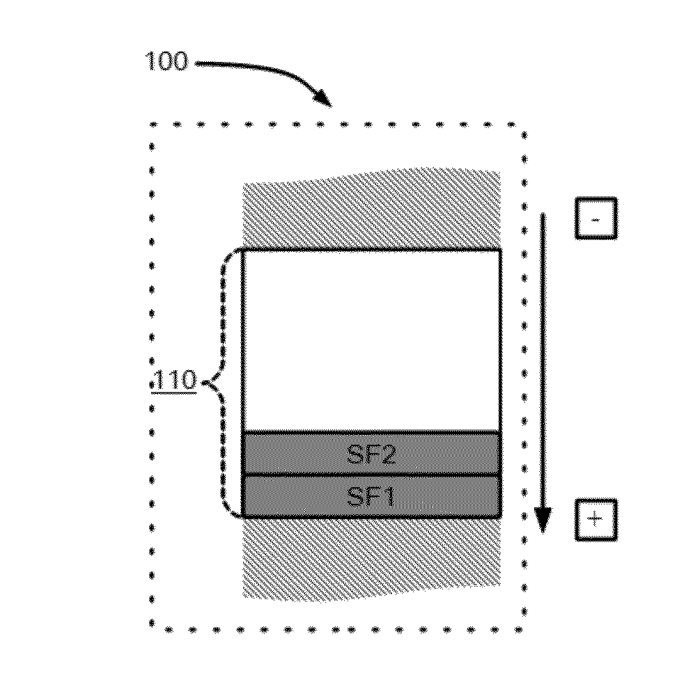
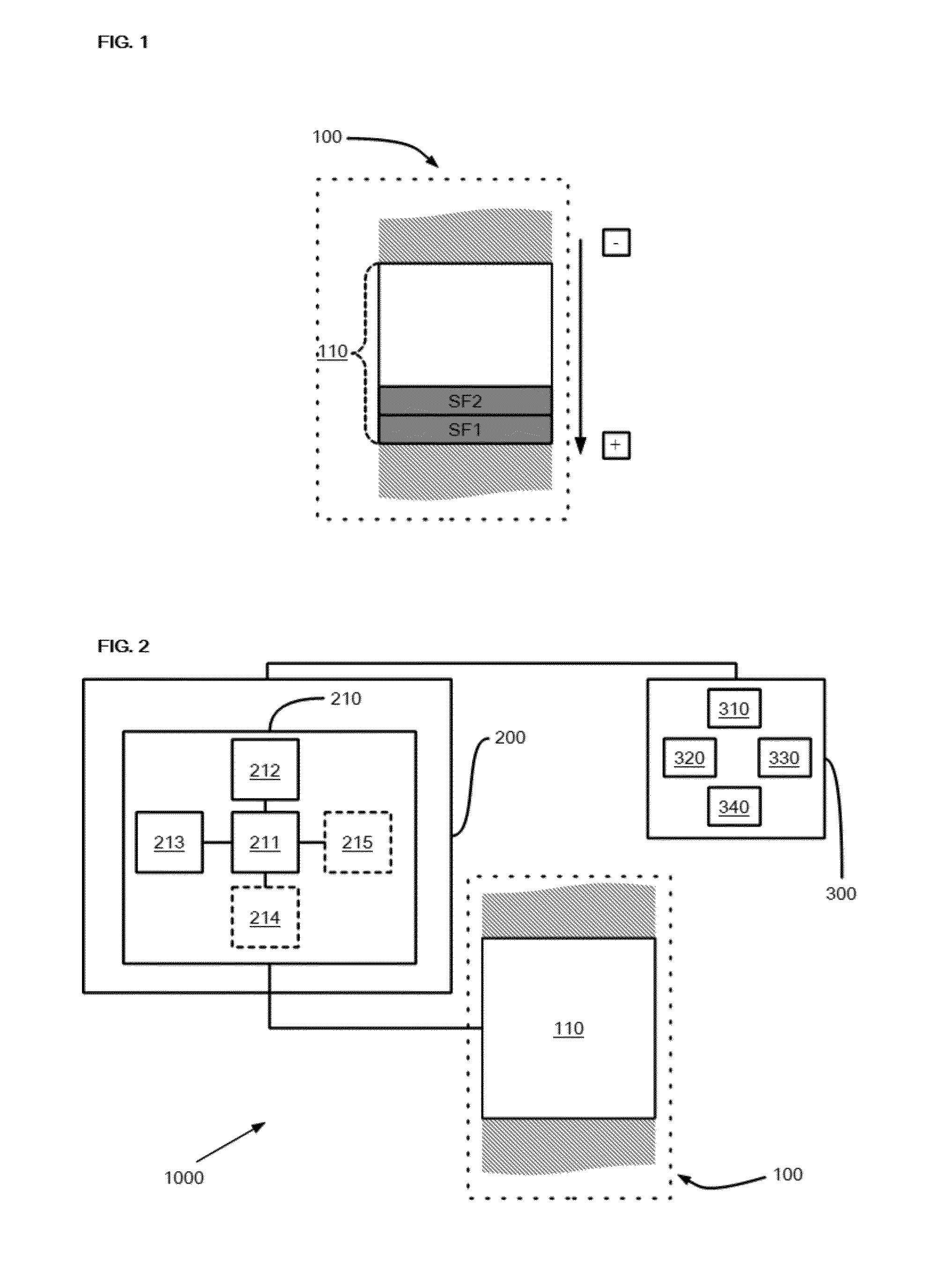
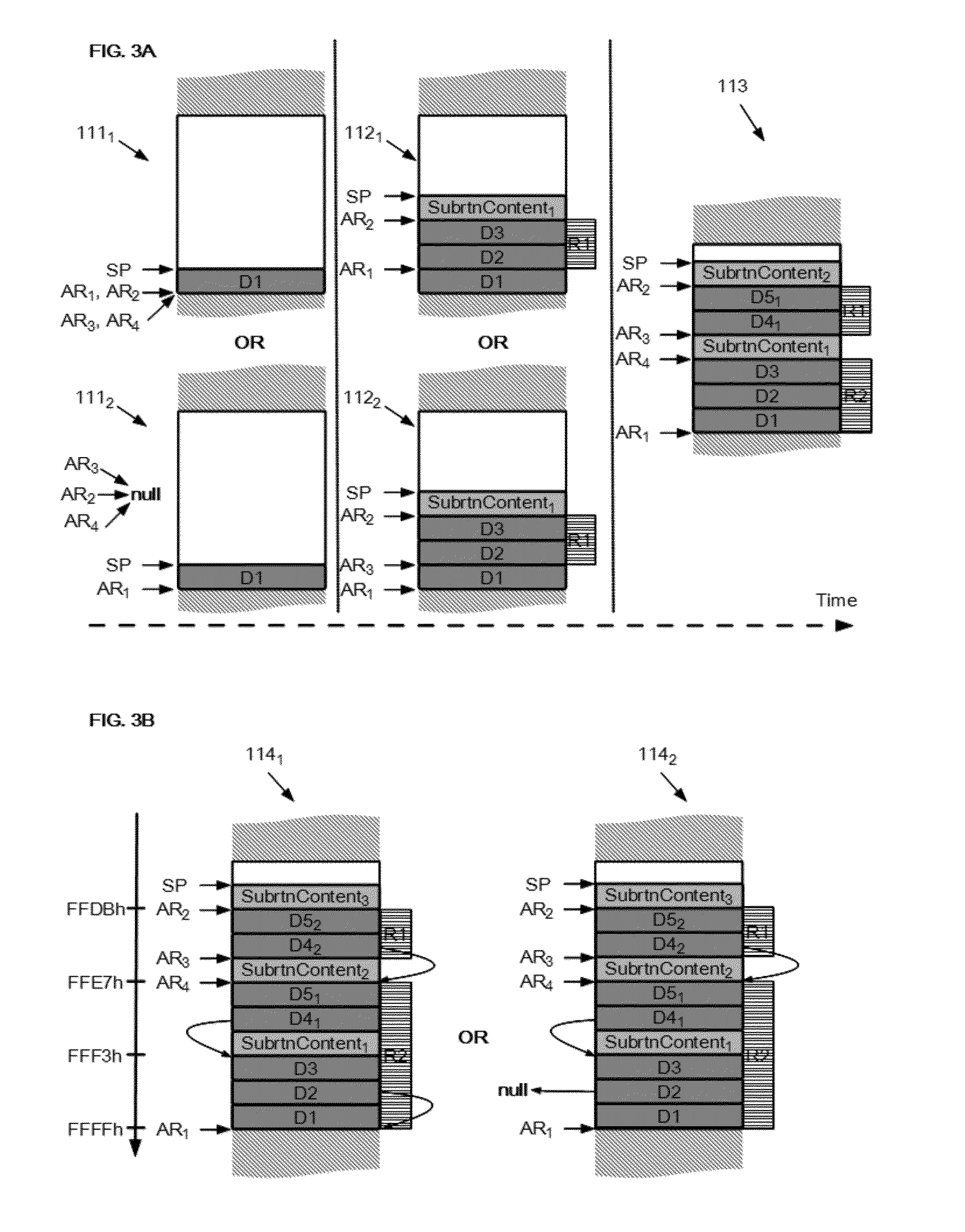
The present invention is a way to protect a part of computer code called a subroutine stack. This invention offers a method for safeguarding the subroutine stack from unauthorized access. The technical effects of this invention include improved security and protection for data stored in computer code.

Problems solved by technology

Subroutine stacks are vulnerable to many security and safety problems.
Security problems typically manifest themselves in external attacks, such as stack buffer overflow attacks, where the attacker intentionally manipulates the saved return address of the subroutine to gain control over the computing system as the subroutine terminates execution and returns control to the software program.
Safety problems are unintended stack manipulation caused by software or hardware faults.
These stack manipulations may have severe impact on the system integrity.
While there are existing protection schemes against the mentioned security problems (e.g., software solutions using the insertion of canary codes), these only offer limited stack protection.
Most computing systems don't provide any protection against the safety issues.
Common protecting mechanisms like memory protection units (MPU) provide access restrictions on static memory ranges and are not suited for the dynamic boundaries required for the protection of subroutine stacks.

Method used


Image

  • Dynamic subroutine stack protection
  • Dynamic subroutine stack protection
  • Dynamic subroutine stack protection

Examples


Embodiment Construction

[0012]Because the illustrated embodiments of the proposed solution may for the most part, be composed of electronic components and circuits known to those skilled in the art, details will not be explained in any greater extent than that considered necessary for the understanding and appreciation of the underlying concepts of the subject application, in order not to obfuscate or distract from the teachings of the subject application.

[0013]However, for the sake of clarity, basic knowledge related to subroutine stacks will be reviewed. First of all, suffice to say that a subroutine stack is a section of a Random Access Memory (RAM) that is structured as a LIFO (Last In-First Out) buffer and which is reserved notably for storage of parameters that are passed by a main program to a subroutine. A subroutine refers to a software program which when its execution has terminated returns control to a main software program that called it. In general, subroutines are mainly called for a single p...


PUM


Abstract

A protection unit of a subroutine stack accessible by a CPU controlled by one main software program, for storing and removing stack frame(s), the stack protection unit being coupleable to the stack and the CPU, comprising:a processor coupled to a first and a second address register;wherein, when a first stack frame is stored onto the stack and the execution of the main software program is suspended by the CPU due to the execution of a subroutine;the processing unit is adapted to set one access rule based on the first and second address registers, preventing:the ongoing subroutine, from accessing a hardware-protected region of the stack, comprising at least one stack frame associated with a return address from which the main software program resumes execution after termination of the execution of the subroutine.A processor, a method and a computer program are also claimed.

Description

CROSS-REFERENCE TO RELATED APPLICATION(S)[0001]The present application is related to co-pending U.S. patent application Ser. No. 14 / 172,638, entitled “DYNAMIC INTERRUPT STACK PROTECTION,” filed on Feb. 4, 2014, the entirety of which is herein incorporated by reference.FIELD OF THE INVENTION[0002]This invention relates to a subroutine stack protection unit, a processor, a method and a computer program for protecting a subroutine stack.BACKGROUND OF THE INVENTION[0003]Subroutines provide a way to perform a particular function at any point in a software program without duplicating the code which implements the function. Whenever a subroutine is called, the current location in the calling program flow is preserved and the subroutine is executed. After the completion of the subroutine, the calling program is resumed at the location where it left off. A calling program is able to pass parameters to a subroutine and retrieve return values upon completion. Subroutines are typically implemen...

Claims


Application Information

Patent Timeline
Patent Type & Authority Patents(United States)
IPC IPC(8): G06F21/00G06F12/14G06F21/52
CPCG06F12/1441G06F21/52G06F12/14G06F2212/1052
Inventor HEISSWOLF, DIRKLEGELEUX, STEPHANIEPACHL, ANDREAS RALPH
Owner NXP USA INC
Learn More