Syringe tip cap

a syringe and tip technology, applied in the field of tip caps, can solve the problems of increasing the difficulty of removing the tip cap, and difficulty for users without dexterity or strength, and achieves the effect of enhancing mechanical advantages and extra leverage for rotating the tip cap

Inactive Publication Date: 2016-08-16
BECTON DICKINSON & CO
View PDF41 Cites 3 Cited by
  • Summary
  • Abstract
  • Description
  • Claims
  • Application Information

AI Technical Summary

Benefits of technology

[0012]In contrast to the prior devices discussed above, it has been found that a tip cap which provides the user with enhanced mechanical advantage for rotating the cap in order to affix it to a syringe can be constructed in ac

Problems solved by technology

However, when overly tightened the tip cap can be difficult to remove or may be damaged.
The autoclaving procedure however, can also have the side effect of interactions between the tip cap to the syringe, thereby further increasing the difficulty in removing the cap.
A problem associated with the prior art tip cap design has been the user must apply a gripping force to grasp the circular cap by exerting a force normal to the cap walls at the point of contact with sufficient force to hold the cap

Method used


Image

  • Syringe tip cap
  • Syringe tip cap
  • Syringe tip cap

Examples


Embodiment Construction

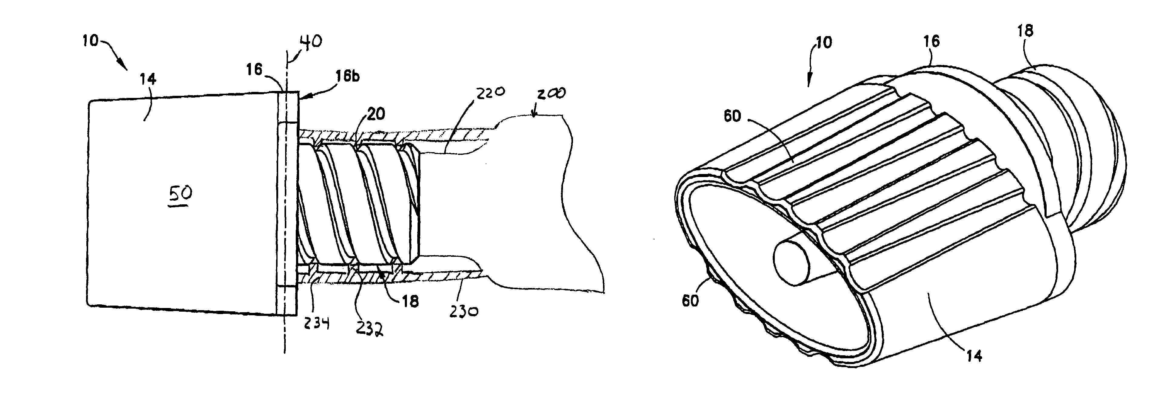
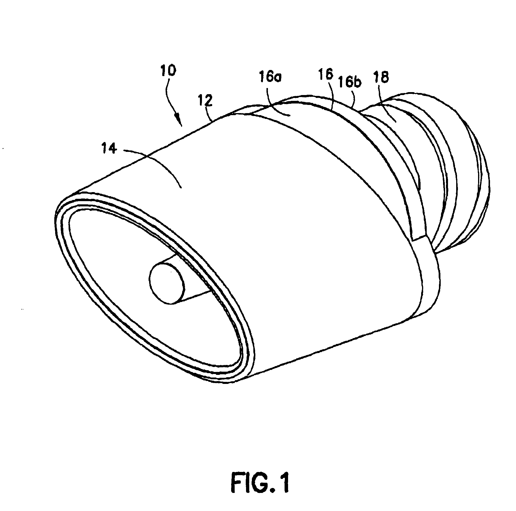
[0030]Referring now to the drawings, FIG. 1 shows a tip cap according to the present invention. In particular, FIG.1 shows a tip cap 10. As can be seen, tip cap 10 includes a cap body 12 having a top wall 14 and a depending sealing base 16, and further includes a shaft 18 for connecting to and disconnecting from a syringe 200. The shaft 18 and the cap body 12 form a single unitary tip cap for receiving a force imparted to the top wall 14 which causes the tip cap 10 to rotate and connect to a syringe body. The top wall 14 is a non-circular tubular structure, extending upwardly from the sealing base 16. The sealing base 16 is a substantially flat surface having an upper surface 16a defining a plane and lower surface 16b. Top wall 14 is rigidly joined to the upper surface 16a, preferably about at least the majority of its perimeter, and the shaft 18 is rigidly joined to the lower surface 16b.

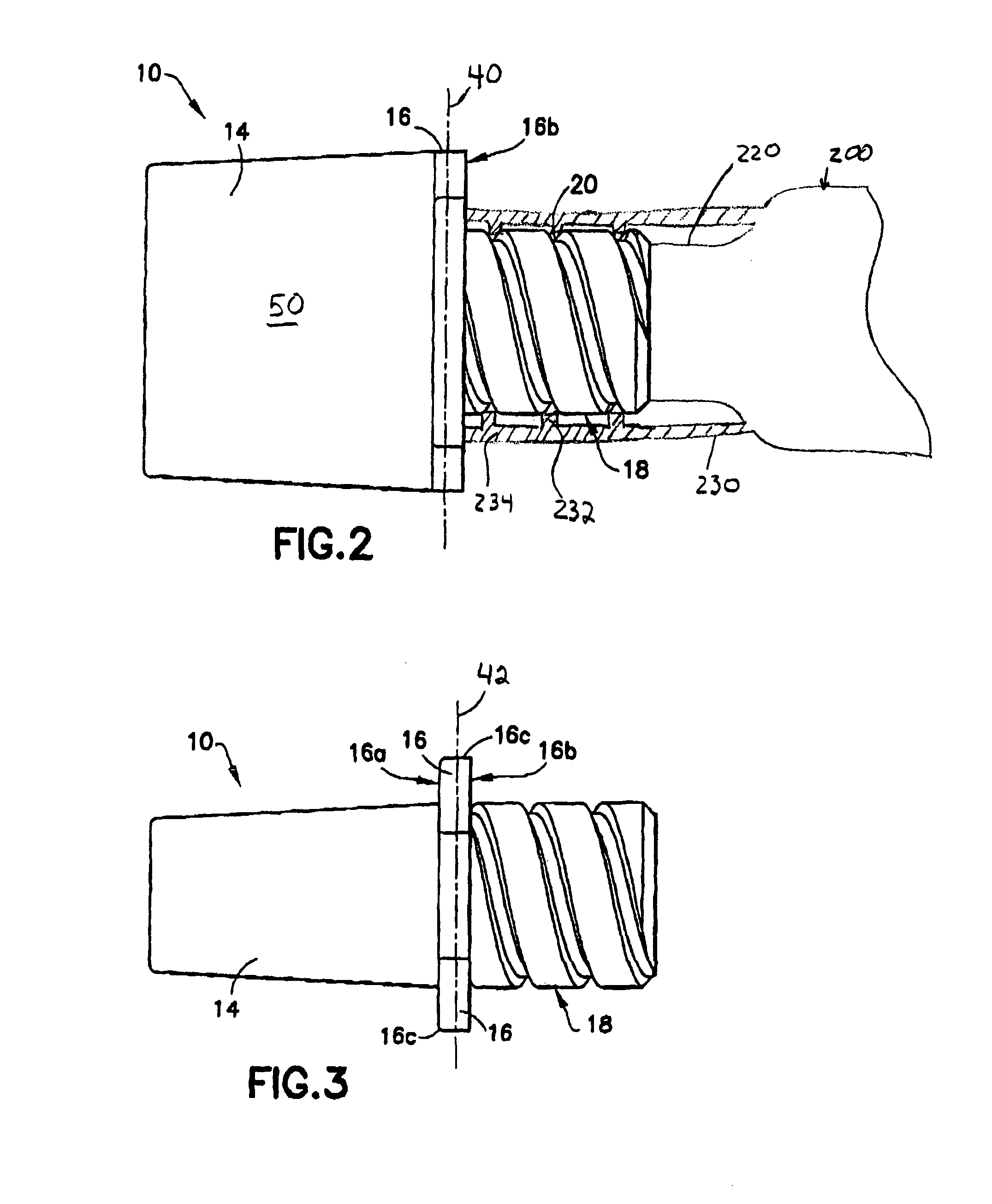
[0031]FIG. 2 depicts the tip cap 10 according to the present invention as viewed from the side...


PUM


Abstract

A tip cap is provided comprising a base portion having an upper surface and a lower surface, a body having a top wall with a non-circular cross-section extending from the upper surface, and a shaft extending from the lower surface. A syringe assembly is provided comprising a syringe comprising a barrel, and a syringe tip, extending through the barrel and a connector provided on the syringe tip. The syringe assembly further comprises a tip cap for sealingly covering the syringe tip and comprising a base portion having an upper surface and a lower surface, a body having a top wall with a non-circular cross-section extending from the upper surface, and a shaft extending from the lower surface having connection means for attaching to the syringe tip.

Description

CROSS-REFERENCE TO RELATED APPLICATIONS[0001]This application is a continuation-in-part of U.S. Design Application No. 29 / 180,313, filed on Apr. 22, 2003, now U.S. Pat. No. D, 493,526 which is incorporated by reference herein.BACKGROUND OF THE INVENTION[0002]1. Field of the Invention[0003]This invention relates to a tip cap for closure of the opening of a liquid filled container, and more particularly, to a tip cap for a syringe.[0004]2. Description of Related Art[0005]Conventional syringes include a barrel having an open proximal end and an opposed distal end. A cylindrical wall extends between the ends and defines a substance retaining chamber. A tip, sometimes referred to as a luer, projects from the distal end of the syringe barrel and includes a narrow passage, which communicates with the substance-retaining chamber of the barrel. A plunger is inserted into the open proximal end of the syringe barrel for sliding fluid-tight engagement with the cylindrical chamber wall. Sliding ...

Claims


Application Information

Patent Timeline
IPC IPC(8): A61M5/00A61M5/31
CPCA61M5/3134A61M2005/3104A61M2205/586
Inventor HWANG, CHARLES G.GROSKOPF, ROGER
Owner BECTON DICKINSON & CO
Why Eureka
Try Eureka