System and methods for positioning a manipulator arm by clutching within a null-perpendicular space concurrent with null-space movement

a technology of null-perpendicular space and null-space movement, applied in the field of surgical and/or robotic devices, systems, and methods, can solve the problems of poor conditioned configuration or collision between the manipulator arm and adjacent arms or personnel, undesirable movement of the more proximal portions etc., and achieve the effect of improving the movement of the manipulator arm and high configurable configuration

Active Publication Date: 2016-08-16
INTUITIVE SURGICAL OPERATIONS INC
View PDF6 Cites 60 Cited by
  • Summary
  • Abstract
  • Description
  • Claims
  • Application Information

AI Technical Summary

Benefits of technology

[0010]The present invention generally provides improved robotic and / or surgical devices, systems, and methods. In many embodiments, the invention will employ highly configurable surgical robotic manipulators. These manipulators, for example, may have more degrees of freedom of movement than the associated surgical end effectors have within a surgical workspace. A robotic surgical system in accordance with the present invention typically includes a manipulator arm supporting a robotic surgical instrument and a processor to calculate coordinated joint movements for manipulating an end effector of the instrument. The joints of the robotic manipulators supporting the end effectors allow the manipulator to move throughout a range of different configurations for a given end effector position and / or a given pivot point location. In one aspect, the invention provides improved movement of the manipulator arm by floating one or more joints within a null-perpendicular space to allow a distal portion of the manipulator arm to be repositioned, such as the distal end effector and / or remote center, while one or more joints are driven within a null-space to effect various other tasks or desired movements, such as collision avoidance or driving the arm toward a desired pose.
[0012]In some embodiments, a manipulator arm may include additional redundant joints that allow for various types of movements within a null-space, such as an auxiliary movement to avoid collisions, move toward a desired pose or to improve conditioning of the joints. In some embodiments, rather than relying on robotic devices that are mechanically constrained to pivot a tool about a fixed point in space, or robotic devices having passive joints which passively pivot about the tissues of a minimally invasive aperture, the present invention may calculate a motion that includes pivoting a link of the manipulator linkage about an aperture site. The degrees of freedom of the robotic linkages supporting the end effectors can allow the linkage to move throughout a range of configurations for a given end effector position, and the systems may drive the linkages to configurations which inhibit collisions involving one or more moving robotic structures. Set-up of highly flexible robotic linkages can be facilitated by processors which drive one or more joints of the linkage while the linkage is being manually positioned. Joint state sensors may be used to sense the manual backdriving movement of the floating joints for use in subsequent calculated joint movements.
[0014]In general, manually backdriving “floating joints” results in movement of various other joints in response and may result in undesirable movement of one or more joints, such as a collision between the manipulator arm and an adjacent arm or personnel, excessive movement, or movement toward an undesirable or a poorly conditioned pose. Manually backdriving a portion of the manipulator arm may utilize the same joints as used in manipulation of the end effector or may include various other selected joints or sets of joints. To provide improved movement of the manipulator arms, the redundant degrees of freedom may be used to determine a movement of the manipulator arm within a null-space concurrent with floating of the end effector or remote center. This may be accomplished by calculating joint movement of the plurality of the joints that “float” a first set of joints within a null-perpendicular space (i.e. joint velocity sub-space which results in movement of the end effector and / or remote center) and drive a second set of joints within a null space (i.e. joint velocity sub-space which maintains the position of the end effector and / or remote center, the null-space being orthogonal to the null-perpendicular space). Driving the second set of joints within the null-space allows for a repeatable and / or a desirable pattern of movement of the manipulator arm during position according to various algorithms in order to provide a desirable movement of a portion of the manipulator arm proximal the distal end effector during manual backdriving movement of the end effector. Typically, these features are included in a clutch mode to allow set-up or docking of the end effector before surgery or repositioning during surgery.
[0020]In some embodiments, a first joint from the first set of joints of the manipulator is a revolute joint coupling the manipulator arm to the base. The desired state of the end effector may include a desired position, velocity or acceleration of the end effector. In yet another aspect of the present invention, a surgical robotic manipulator with a proximal revolute joint and a distal parallelogram linkage is provided, the pivotal axis of the revolute joint substantially intersecting with the axis of the instrument shaft of the end effector, preferably at a remote center if applicable. The system further includes a processor having a controller coupling the input to the manipulator arm and configured to calculate a movement of the plurality of joints in response to a user input command. The system may include a clutch mode in which a first set of joints of the plurality of joints float within a null-perpendicular space to allow a patient side assistant to move the end effector or a remote center about which the end effector moves to a desired position for surgery while one or more joints of a second set of joints are driven within a null-space according to one or more algorithms to effect various tasks, such as collision avoidance, pose preference, or to improve conditioning of the manipulator arm. In any of the embodiments described herein, each of the first and second set of joints may include one or more joints and the first and second joints may include one or more joints in common or may be entirely different sets of joints.

Problems solved by technology

Since the manipulator arm is highly configurable, often including redundant joints such that a range of configurations and joints states are available for a given state of the end effector or remote center, movement of distal portion, such as an end effector, during set-up may result in undesirable movement of proximal portions of the manipulator arm resulting in poorly conditioned configurations or collisions between the manipulator arm and adjacent arms or personnel.
For example, when inserting or positioning the tool tip or distal end effector of the manipulator within a cannula at the minimally invasive aperture before surgery, referred to herein as “docking,” movement of the tool tip or end effector may results in undesirable movement of the more proximal portions of the manipulator arm.

Method used


Image

  • System and methods for positioning a manipulator arm by clutching within a null-perpendicular space concurrent with null-space movement
  • System and methods for positioning a manipulator arm by clutching within a null-perpendicular space concurrent with null-space movement
  • System and methods for positioning a manipulator arm by clutching within a null-perpendicular space concurrent with null-space movement

Examples


Embodiment Construction

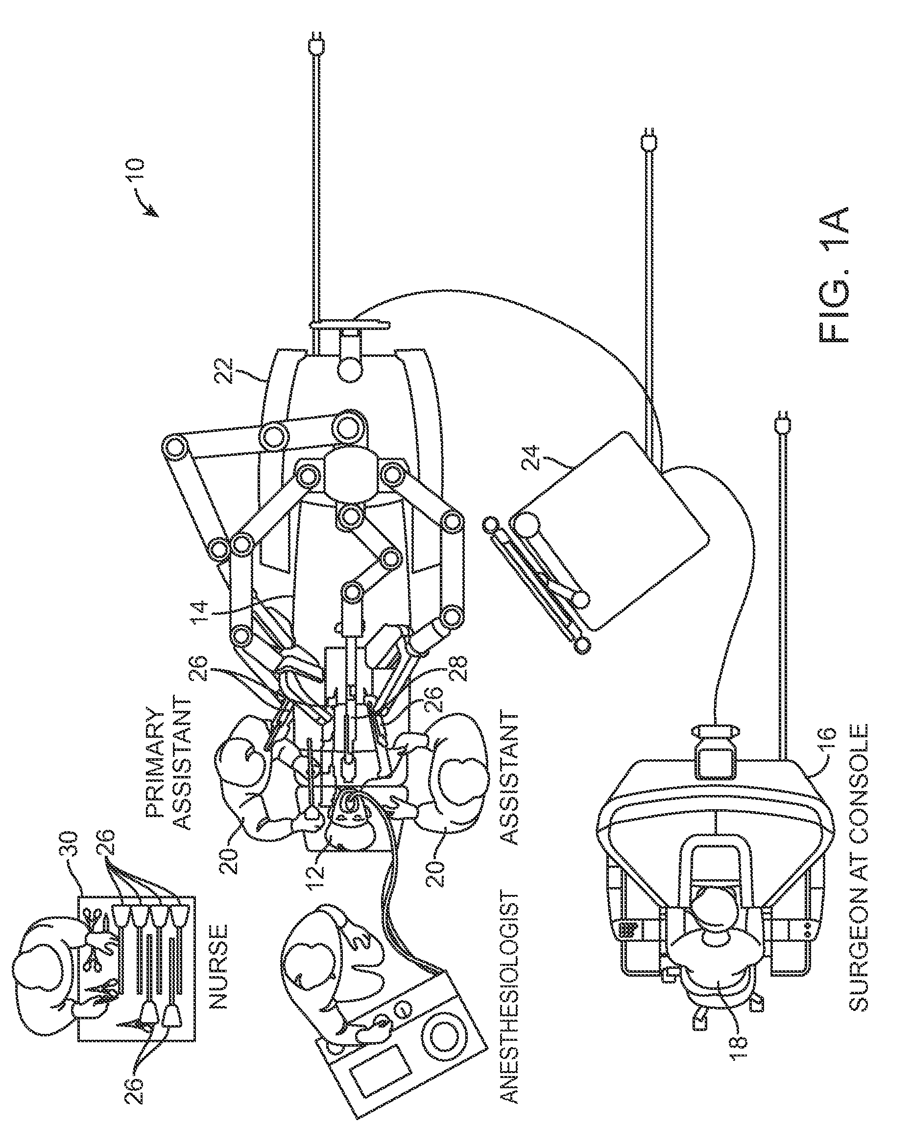
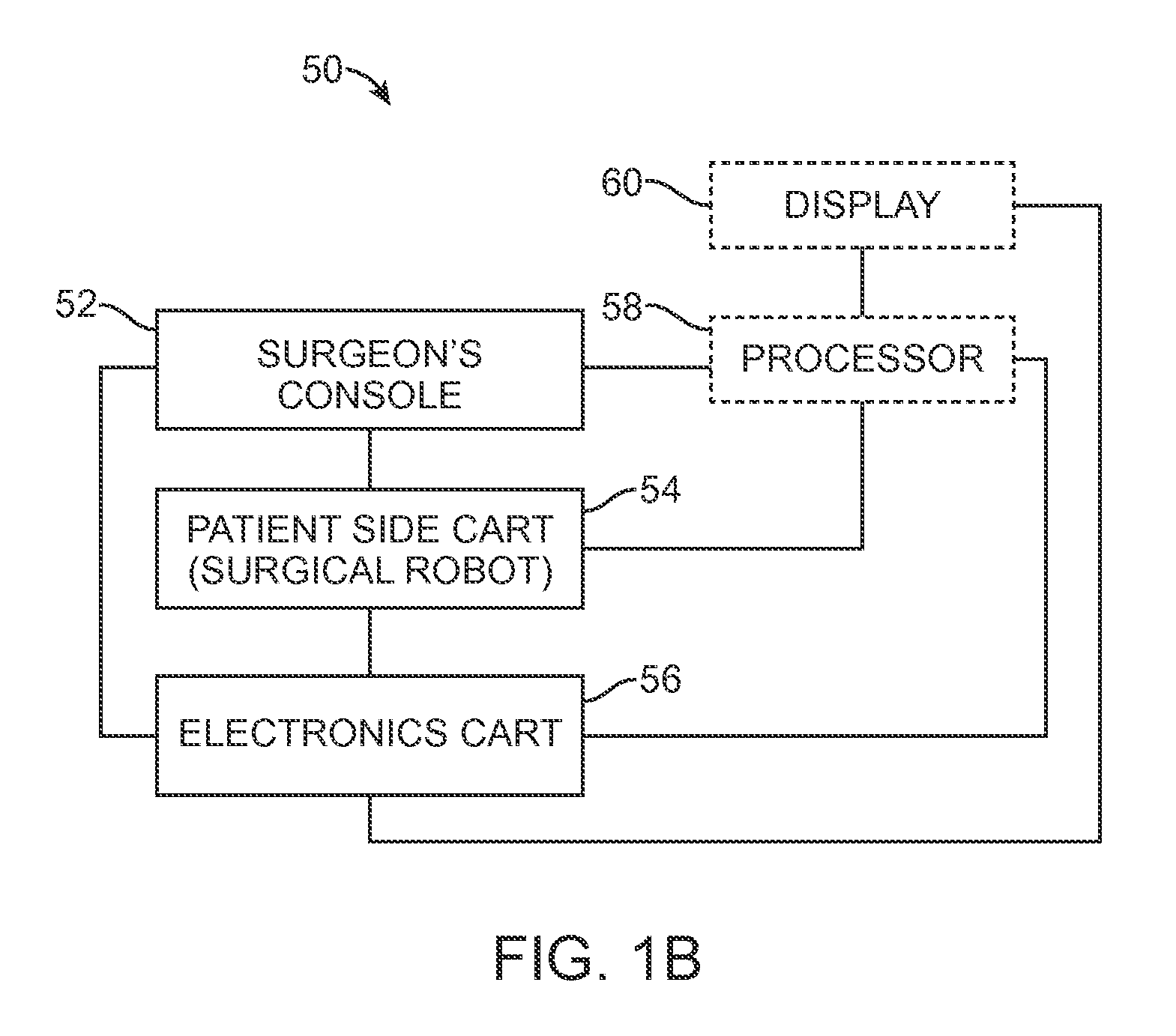
[0042]The present invention generally provides improved surgical and robotic devices, systems, and methods. The invention is particularly advantageous for use with surgical robotic systems in which a plurality of surgical tools or instruments may be mounted on and moved by an associated plurality of robotic manipulators during a surgical procedure. The robotic systems will often comprise telerobotic, telesurgical, and / or telepresence systems that include processors configured as master-slave controllers. By providing robotic systems employing processors appropriately configured to move manipulator assemblies with articulated linkages having relatively large numbers of degrees of freedom, the motion of the linkages can be tailored for work through a minimally invasive access site. The large number of degrees of freedom allows a system operator, or an assistant, to reconfigure the linkages of the manipulator assemblies while maintaining the desired end effector state, optionally in pr...


PUM


Abstract

Devices, systems, and methods for positioning an end effector or remote center of a manipulator arm by floating a first set of joints within a null-perpendicular joint velocity sub-space and providing a desired state or movement of a proximal portion of a manipulator arm concurrent with end effector positioning by driving a second set of joints within a null-space orthogonal to the null-perpendicular space. Methods include floating a first set of joints within a null-perpendicular space to allow manual positioning of one or both of a remote center or end effector position within a work space and driving a second set of joints according to an auxiliary movement calculated within a null-space according to a desired state or movement of the manipulator arm during the floating of the joints. Various configurations for devices and systems utilizing such methods are provided herein.

Description

CROSS-REFERENCES TO RELATED APPLICATIONS[0001]This application is a Non-Provisional of and claims the benefit of priority from U.S. Provisional Patent Application No. 61 / 799,920 filed on Mar. 15, 2013 and entitled “Systems and Methods for Positioning a Manipulator Arm by Clutching within a Null-Perpendicular Space Concurrent with Null-Space Movement”, the full disclosure of which is incorporated herein by reference.[0002]The present application is generally related to the following commonly-owned applications: U.S. application Ser. No. 12 / 494,695 filed Jun. 30, 2009, entitled “Control of Medical Robotic System Manipulator About Kinematic Singularities;” U.S. application Ser. No. 12 / 406,004 filed Mar. 17, 2009, entitled “Master Controller Having Redundant Degrees of Freedom and Added Forces to Create Internal Motion;” U.S. application Ser. No. 11 / 133,423 filed May 19, 2005 (U.S. Pat. No. 8,004,229), entitled “Software Center and Highly Configurable Robotic Systems for Surgery and Oth...

Claims


Application Information

Patent Timeline
Patent Type & Authority Patents(United States)
IPC IPC(8): B25J18/00B25J9/16
CPCB25J9/1638B25J18/007B25J9/1607A61B34/30A61B34/37A61B34/32B25J9/1666
Inventor HOURTASH, ARJANGSWARUP, NITISH
Owner INTUITIVE SURGICAL OPERATIONS INC
Why Eureka
Try Eureka