Method for connecting connection piece to thermally insulated conduit pipe

a technology of thermal insulation and connection pieces, which is applied in the direction of thermal insulation, heat exchange apparatus, flexible pipes, etc., can solve the problems of not yielding optimal methods, and achieve the effects of uniform attachment of the connection piece, good sealing, and better adaptation to the position of the end fa

Inactive Publication Date: 2016-08-16
BRUGG ROHR AG HLDG
View PDF14 Cites 0 Cited by
  • Summary
  • Abstract
  • Description
  • Claims
  • Application Information

AI Technical Summary

Benefits of technology

[0006]As a result of the connection body being pressed by the clamping sleeve indirectly against the internal pipe by means of the retaining ring, a good fit of the connection body on the front side of the internal pipe is achieved due to the elasticity of the retaining ring. Another advantage involves the clamping sleeve, which applies a circumferential stress or radial force to the internal pipe, thus fixing the plug sleeve. A circular cylindrical shape of the internal pipe can thus also be forced with the clamping sleeve in the connection area, which promotes the tightness of the connection without the need to expose the internal pipe for that purpose. The insulating layer and the casing therefore remain intact in the connection area, and the work steps for the removal thereof are eliminated. The plug sleeve of the connection piece is thus fastened in a substantially exactly circular cylindrical internal pipe and fixed therein in a sealing manner. The clamping sleeve absorbs the radial force of the plug sleeve on the internal pipe.
[0007]In one preferred embodiment, the retaining ring also constitutes an indicator that makes it possible to determine whether the clamping sleeve is inserted far enough into the conduit pipe and screwed far enough onto the internal pipe. The retaining ring is preferably made of plastic, and the other parts of the connection body are also preferably made of plastic. In another preferred embodiment, the plug sleeve is provided with several circumferential external ribs that are spaced from the front end of the plug sleeve at alternating distances along its periphery. If need be, other formations such as nubs or points are provided in addition to or instead of the ribs. For one, the ribs form seals for the fluid transported in the internal pipe. For another, they provide anti-twist protection against the rotation of the connection piece and the internal pipe, which is also the function of the other formations. In addition, the embodiment of the ribs facilitates the insertion of the plug sleeve into the internal pipe.
[0010]Since the connection body is pressed with its stop against the end face of the internal pipe indirectly via the retaining ring, better adaptation to the position of the end face of the internal pipe is achieved as a result of the elasticity of the retaining ring. The embodiment of the clamping sleeve with an internal thread makes screwing onto the internal pipe possible, which enables a more uniform attachment of the connection piece—and more precise attachment in terms of the pressing force of the connection body against the internal pipe. At the same time, the clamping sleeve offers the advantage of the calibration of the internal pipe, so that the plug sleeve can lie in a uniform manner that provides a good seal. These advantages also apply to the method of connecting the connector piece to a thermally insulated conduit pipe.
[0011]Preferably, the plug sleeve is embodied integrally with the connection body, and the means of attachment of the retaining ring is an attachment flange that engages in a groove in the connection body. Both measures, whether implemented individually or together, result in an especially simple construction. Furthermore, it is preferred that the retaining ring form an indicator, particularly by means of a color of the retaining ring that differs from the connection body, by means of which it can be indicated that the clamping sleeve has been screwed correctly or sufficiently into the conduit pipe. This enables the person establishing the connection of conduit pipe and connection piece to ensure in a simple manner that they have screwed the clamping sleeve in such that the connection is sufficiently solid. It is also preferred that the ribs be spaced from the front end of the plug sleeve at alternating distances, which secures the abovementioned advantages. It is also preferred that the clamping sleeve have at least one gripping means for the positive gripping of a tool, which enables the screwing-in of the clamping sleeve on the internal pipe and between the latter and the thermal insulation using a suitable tool.

Problems solved by technology

It is evident that this method does not yield optimal results for conduit pipes with an end face that is not exactly perpendicular to the longitudinal axis of the pipe.

Method used


Image

  • Method for connecting connection piece to thermally insulated conduit pipe
  • Method for connecting connection piece to thermally insulated conduit pipe
  • Method for connecting connection piece to thermally insulated conduit pipe

Examples


Embodiment Construction

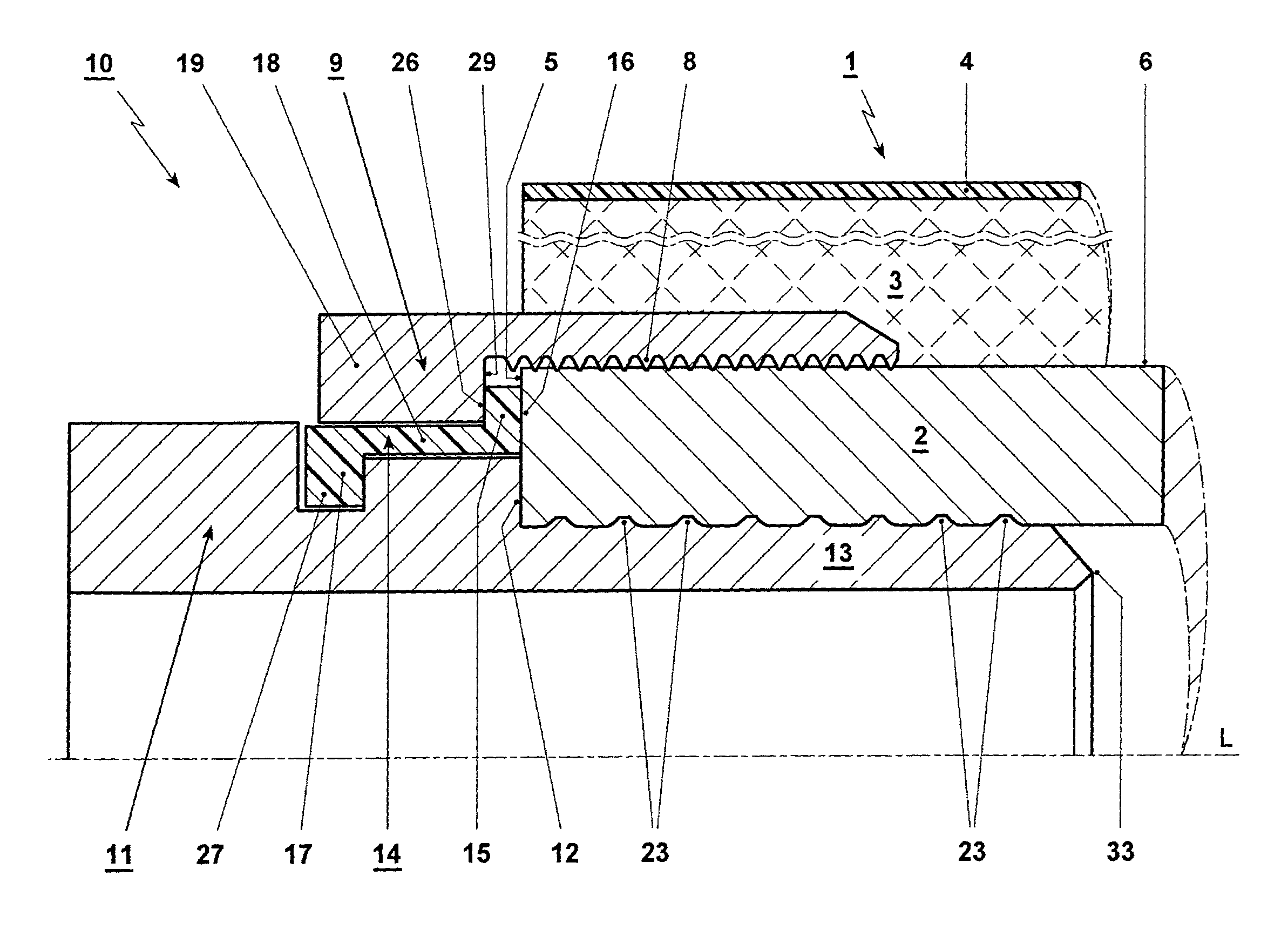
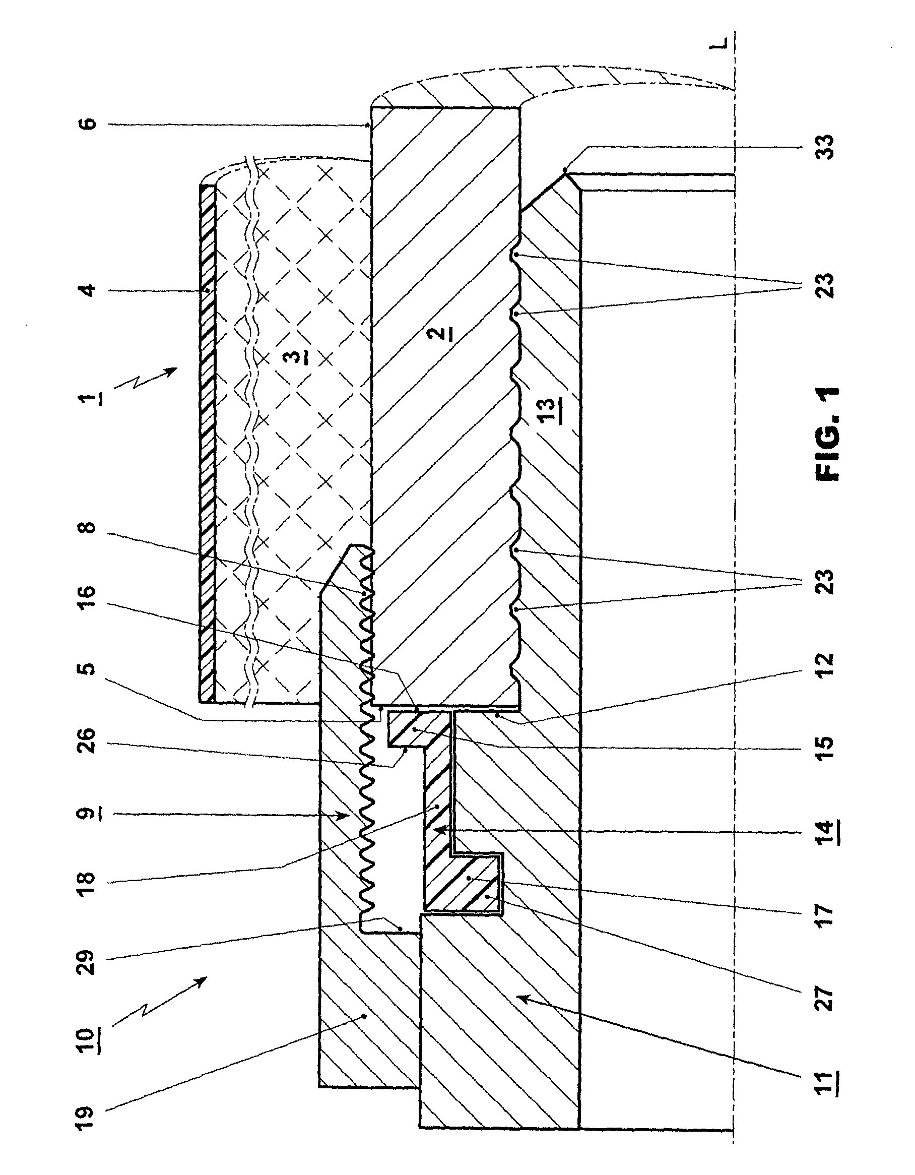
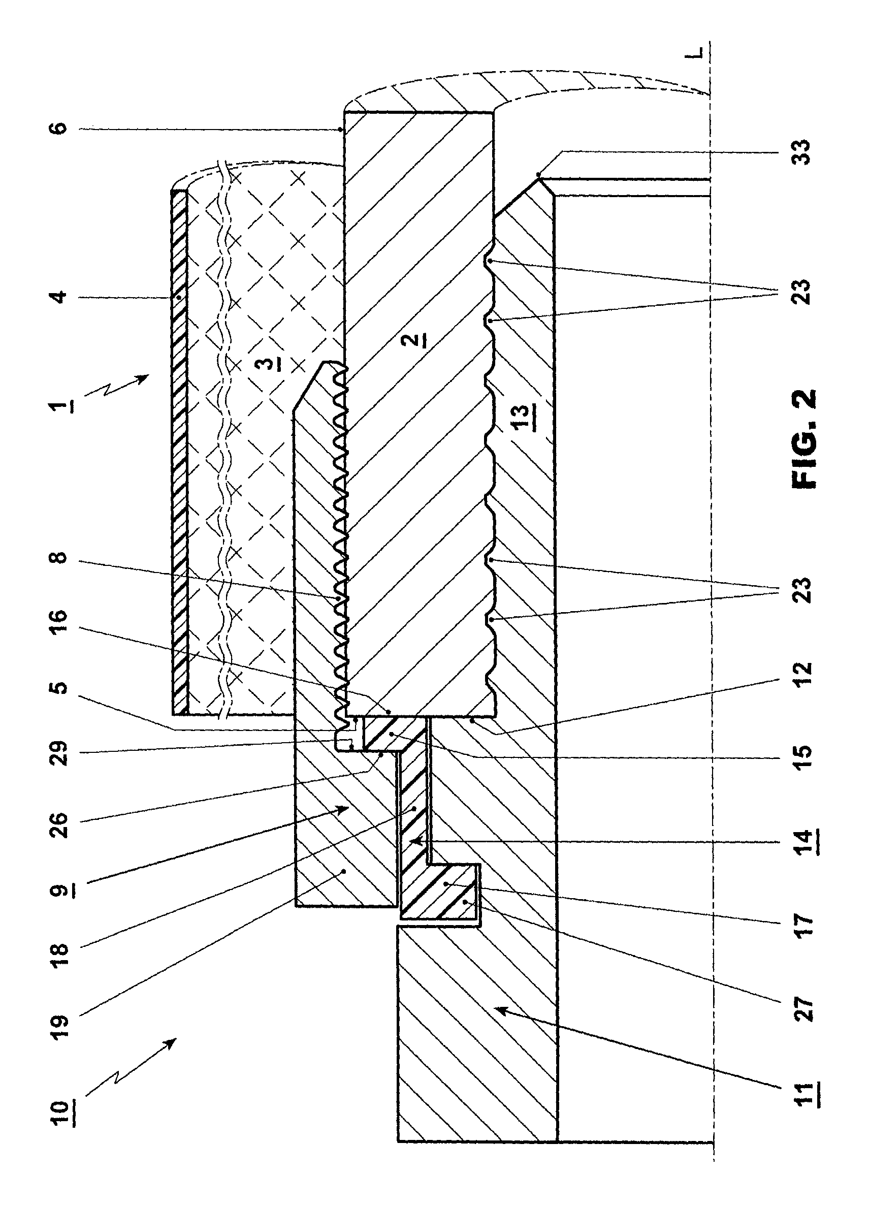
[0017]FIGS. 1 and 2 show a sectional representation through the end region of a conduit pipe, with the longitudinal axis L of the conduit pipe lying on the sectional plane. To simplify the figure, only a portion of the rotationally symmetrical conduit pipe and of the connection piece (which is substantially rotationally symmetrical in the connection area) are shown above the longitudinal axis L. The connection piece can have any known design or function as a pipe coupling or fitting or armature and be commensurately embodied with the conduit pipe outside of its depicted connection area. In particular, the connection piece can be embodied the same on another end as on the end shown. The conduit pipe has a thermal insulation (not shown in full thickness) that respectively encloses the internal pipe, and preferably an external casing. Particularly, the thermal insulation and the external casing are corrugated. Such a conduit pipe can particularly be embodied and manufactured according ...


PUM

PropertyMeasurementUnit
coloraaaaaaaaaa
distancesaaaaaaaaaa
thermally insulatingaaaaaaaaaa

Abstract

In order to connect a connection piece (10), which is, for example, a pipe coupling or a mounting or a fitting, to a thermally insulated conduit pipe (1), a clamping sleeve (9) with an internal thread (8) is screwed in between the internal pipe (2) of the conduit pipe and the insulation layer (3) of the conduit pipe. A connection body (11) with a plug sleeve (13) is arranged in the internal pipe beforehand. The clamping sleeve (9) acts indirectly on the connection piece (10) by way of a retaining ring (14) in order to press the connection piece against the end face (5) of the internal pipe (2). In this way, the distance between the insulation layer (3) and the casing (4) of the conduit pipe is dispensed with and inaccuracies when cutting the conduit pipe to length can be compensated.

Description

CROSS REFERENCE TO RELATED APPLICATIONS[0001]This application claims the priority of PCT Application No. PCT / CH2013 / 000012, filed on Jan. 21, 2013 and Swiss Patent Application No. 98 / 12 filed on Jan. 23, 2012, the disclosures of which are incorporated herein by reference in their entirety.TECHNICAL FIELD[0002]The invention relates to a method for connecting a connection piece to a thermally insulated conduit pipe, which conduit pipe comprises an internal pipe, an insulating layer and preferably an external casing, the connection piece having a connection body with a plug sleeve that is fastened in the internal pipe, a stop of the stop body coming to rest on the end face of the internal pipe, and a clamping sleeve being introduced from the end face of the internal pipe between the outer wall of the internal pipe and the insulating layer. Moreover, the invention relates to a connection piece which is intended and designed to execute the method and hence to connect to a thermally insul...

Claims


Application Information

Patent Timeline
Patent Type & Authority Patents(United States)
IPC IPC(8): F16L11/00F16L33/22F16L59/18B23P19/04F16L11/15
CPCF16L59/181F16L33/223B23P19/04F16L11/15Y10T29/49952
Inventor SCHALLER, WERNER
Owner BRUGG ROHR AG HLDG
Why Eureka
Try Eureka