Epicyclic reduction gear, notably for turbomachine

a technology of cyclic reduction and gear, which is applied in the direction of gearing details, belts/chains/gears, gear lubrication/cooling, etc., can solve the problems of increasing dimensions and mass, difficult to control the oil flow supplied to the journal bearing in case of breakdown, and difficult to produce planet carriers. , to achieve the effect of simple, efficient and cost-effectiv

Active Publication Date: 2016-08-30
SAFRAN TRANSMISSION SYST
View PDF17 Cites 4 Cited by
  • Summary
  • Abstract
  • Description
  • Claims
  • Application Information

AI Technical Summary

Benefits of technology

[0012]Such individual elements are easily achieved and form, after assembly, a continuous passage formed of the series of passages of the various assembled elements. The higher the number of elements the more significant the pressure drop in the passage of the device. Besides, the passage of each element does not necessarily have a much reduced section, which makes it possible to prevent the clogging of the device by particles present in the fluid.
[0016]Advantageously, the passage of each element has the general shape of a labyrinth and comprises at least one bent area, which makes it possible to increase the pressure drops without having to reduce the passage section.
[0021]Besides, the device may comprise several cylindrical elements having the same structure, with the inlet and the outlet of the passage of each said element being angularly spaced apart by a predetermined angle, with the positioning means making it possible to angularly move two adjacent elements by the same angle value.
[0026]In case of failure, the flow of oil that enters the chamber becomes null and the volume of oil in the chamber decreases and no longer reaches the upper area: the oil can no longer escape through the main passage, but only through the secondary passage. The oil flow feeding the journal bearing is thus reduced, but is sufficient to prevent seizing of the bearing for a limited period of time necessary for example for starting an auxiliary pump or stopping the turbomachine (degraded operation of the journal bearing).
[0027]The invention further makes it possible to provide a secondary passage having a pressure loss sufficiently high and controlled to generate a low flow of oil in case of failure, while avoiding the risk of clogging of the secondary passage by particles contained in the oil.

Problems solved by technology

The structure of such accumulators and the locations thereof make the production of the planet carrier difficult and increase the dimensions and the mass thereof.
Furthermore, controlling the oil flow supplied to the journal bearing in case of breakdown is relatively difficult.
In this application, however, a passage having a sufficiently small diameter over a relatively long length (e.g. a length of approximately 100 times the diameter of the passage) is not only difficult to realize but it is also subject to clogging by particles contained in the oil circuit.
Another solution would be to use a strainer at the inlet of the passage so as to limit the flow rate but in this case too, a risk of clogging of the strainer by the particles exists.

Method used


Image

  • Epicyclic reduction gear, notably for turbomachine
  • Epicyclic reduction gear, notably for turbomachine
  • Epicyclic reduction gear, notably for turbomachine

Examples


Embodiment Construction

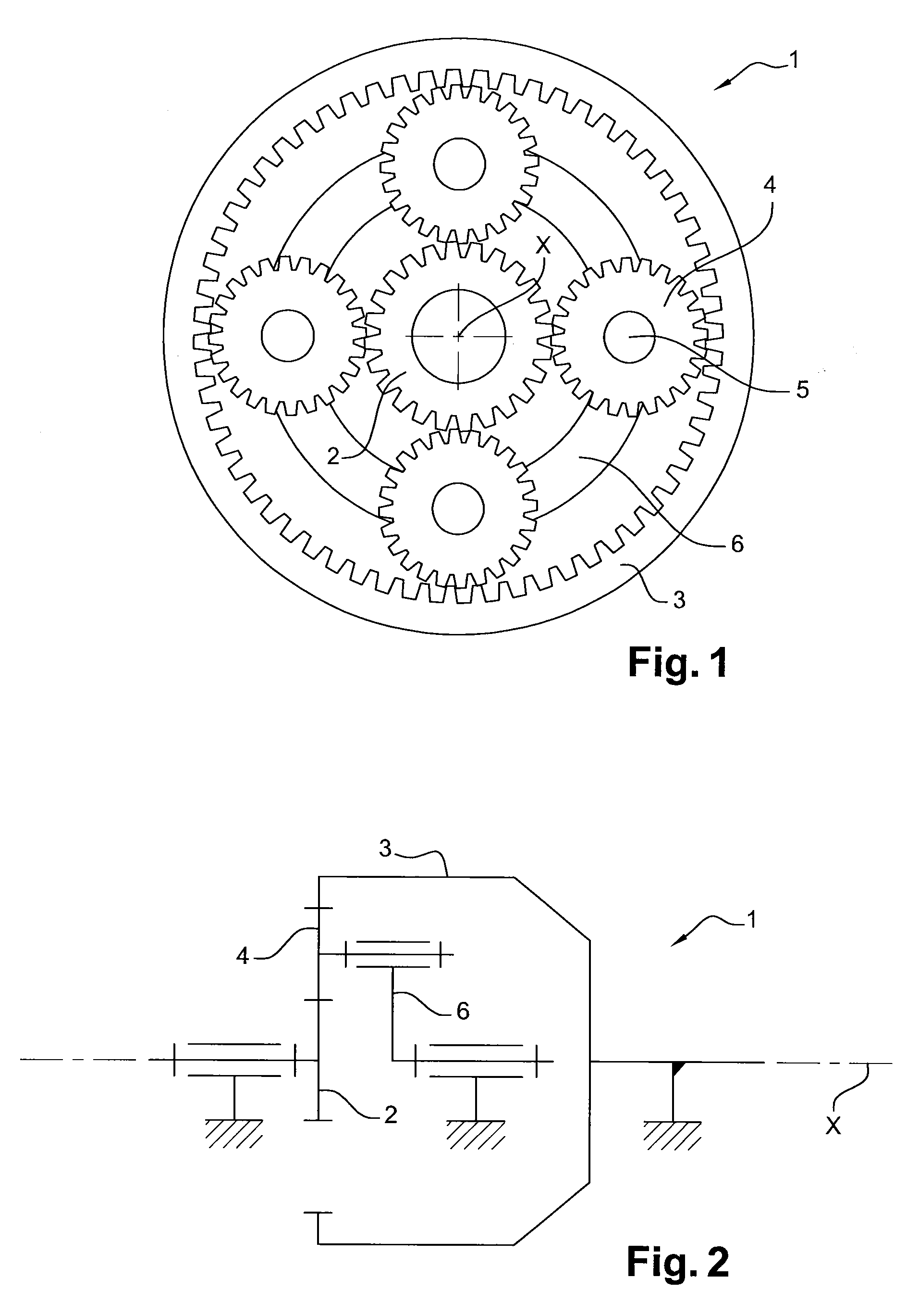
[0038]FIGS. 1 and 2 schematically illustrate the structure of an epicyclic reduction gear 1 according to the invention. The latter conventionally comprises an internal sun gear 2 (also called the sun) and an external sun gear 3 (also called an orbit gear) which are coaxial. The internal sun gear 2 is movable in rotation about its axis, with the external sun gear 3 being stationary. The reduction gear further comprises planet gears 4 mounted to be movable in rotation on pivots 5 of a planet carrier 6. Each planet gear 4 meshes with both the internal sun gear 2 and with the external sun gear 3. The planet carrier 6 is able to pivot about the axis X of the internal sun gear 2 and the external sun gear 3.

[0039]The inlet is formed by the internal sun gear 2 and the outlet is formed by the planet carrier 6.

[0040]In a turbomachine, epicyclic reduction gears are used in particular as speed reducers for reducing the speed of rotation of the fan rotor, regardless of the rotational speed of th...


PUM


Abstract

An epicyclic reduction gear, for example for a turbomachine, including a device forming a fluid circulation passage configured to generate a pressure drop, created by stacking at least two elements. Each element includes a passage for carrying fluid configured to generate a pressure drop and including an inlet and an outlet. The outlet, or inlet, of the passage of one of the elements is, respectively, connected to the inlet, or to the outlet, of the passage of the other element.

Description

[0001]The present invention relates to an epicyclic reduction gear, in particular for a turbomachine, comprising a device forming a fluid circulation passage adapted to generate a pressure drop.BACKGROUND OF INVENTION[0002]An epicyclic conventionally comprises an internal sun gear and an external sun gear which are coaxial, with the internal sun gear being movable in rotation about its axis, with the external sun gear being stationary, with at least one planet gear being mounted to be movable in rotation on a planet carrier and meshing with both the internal sun gear and the external sun gear, with the planet carrier being able to pivot about the axis of the internal sun gear and the external sun gear. The inlet is typically formed by the internal sun gear and the outlet is formed by the planet carrier. The outer planet is also called an orbit gear.[0003]In a turbomachine, epicyclic reduction gears are used in particular as speed reducers for reducing the speed of rotation of the fa...

Claims


Application Information

Patent Timeline
Patent Type & Authority Patents(United States)
IPC IPC(8): F16H57/04
CPCF16H57/0442F16H57/045F16H57/0479F16H57/0486F16H57/0435F16H57/04
Inventor FERAUD, BENJAMINBECK, GUILLAUMEMORELLI, BORISPELTIER, JORDANE
Owner SAFRAN TRANSMISSION SYST
Why Eureka
Try Eureka